
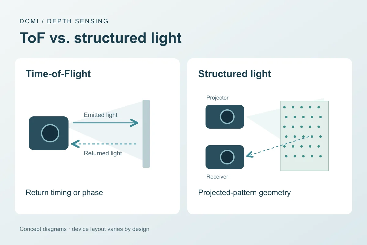
The main difference between ToF and structured light is how they calculate distance. ToF measures light's return time or phase delay. Structured light uses a projected pattern and calibrated viewing geometry to triangulate surface points. For continuous scene depth, such as robot perception or people tracking, ToF is a useful starting point. For detailed shape capture in a controlled inspection or picking station, industrial structured light deserves an early place on the shortlist.
Those are starting points for selection. A moving conveyor, reflective part or sunlit installation can change which specific system fits. This comparison focuses on depth cameras; a single-point ToF range sensor provides a different output from an image-producing camera. RGB-D describes the combination of color and depth, and does not by itself identify the depth-sensing method.
How the measurements differ
A ToF device estimates distance from the travel time or phase delay of returned light. A structured-light system projects a known pattern and calculates depth from its observed deformation or displacement. The ToF receiver may provide a per-pixel depth map; structured light relies on resolving the projected pattern, its calibration, and its geometry.
ToF measures the return of light
Direct ToF (dToF) estimates the delay between an emitted pulse and its return. In the ideal round-trip model, range equals the speed of light multiplied by the measured delay, divided by two. The factor of two accounts for the outward and return paths. Indirect ToF (iToF) instead estimates the phase shift of modulated illumination and converts it to distance. A repeating modulation signal introduces range ambiguity that the device's measurement scheme must resolve.
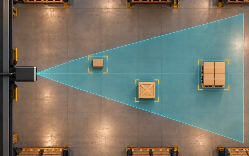
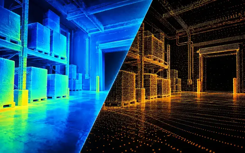
An area ToF camera performs these measurements across its sensor to form a depth image. It can illuminate a scene without encoding each surface point in a spatial pattern. That makes it a practical route for scene depth, including surfaces with little visible texture. Its output still depends on receiving enough usable light. Acquisition settings and processing determine how quickly the host receives a usable result.
Structured light measures geometry
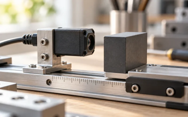
A projector places a known pattern, such as dots or stripes, on the scene. A camera observes that pattern from a different position. The system identifies which projected feature corresponds to an observed image feature, then uses the calibrated projector-camera geometry to locate the surface point. Their separation forms a baseline for triangulation.
Moving a surface changes where its projected features appear in the camera image. The system turns that displacement into depth. Both the projector and the observing camera need access to the measured region, so occlusions and projector shadows matter around deep recesses and overlapping parts. Active stereo also may project texture, but typically calculates correspondence between two camera images; a projector alone does not make every active depth camera the same architecture.
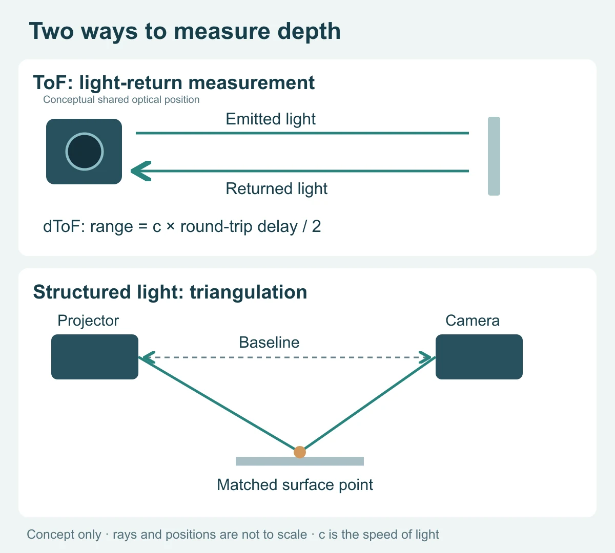
Figure 1. ToF obtains range from a light-return measurement; structured light obtains surface position from calibrated geometry. The diagrams are conceptual and are not to scale.
Single-shot and multiple-pattern structured light
Structured light includes different acquisition designs. A spatially encoded pattern can be decoded from one capture. A temporal method projects several patterns in sequence and combines the observations to identify correspondences. The latter can support detailed surface reconstruction, but movement during the sequence can disrupt those correspondences. Single-shot and specialized motion-capable structured-light systems are available, so treating all structured light as suitable only for stationary objects would be misleading.
Practical comparison
| Question | ToF | Structured light |
|---|---|---|
| What creates depth? | Measured return timing or phase | Observed geometry of a projected pattern |
| What can limit it? | Weak returns, multipath, ambient light, phase ambiguity for some designs | Pattern visibility, occlusion, surface behavior, ambient light |
| Which is better outdoors? | Depends on the exact emitter, optics, receiver, and test conditions | Depends on pattern power, receiver, and test conditions |
| Which is faster or more accurate? | Cannot be decided from the technology name alone | Cannot be decided from the technology name alone |
Why accuracy, speed and lighting differ
Accuracy and spatial detail answer different questions
Depth accuracy describes agreement with a reference distance or shape. Repeatability describes the spread of repeated measurements. Spatial detail describes how well adjacent features or edges can be distinguished. A high pixel count or a stable reading alone does not establish all three.
Industrial structured-light systems are worth evaluating when small features and detailed surface geometry drive the task. Their results depend on optics, baseline, correspondence quality and calibration. ToF is useful when the task prioritizes a scene depth stream; low return signal, mixed foreground-background pixels and indirect reflections can affect the useful data. Neither label establishes a universal accuracy ranking. Compare candidates at the same distance, field of view and target conditions.
Motion depends on the acquisition window
For a conveyor or moving person, compare the time over which observations are collected, as well as the output frame rate. A multiple-pattern scan may combine images of different object positions. An iToF depth frame can also combine several phase samples, so ToF is not automatically free from motion artifacts. A short acquisition reduces the time available for collecting light, creating a practical trade-off with signal quality.
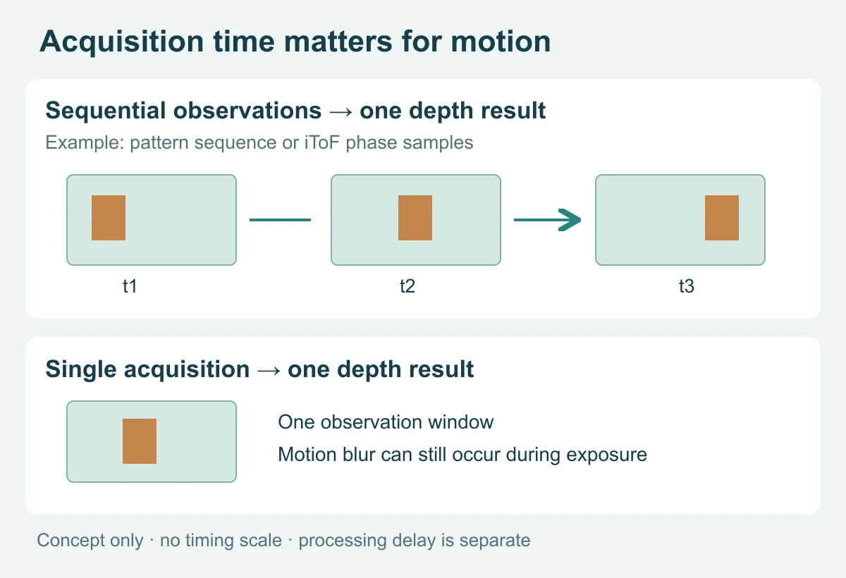
Figure 2. Movement between observations can affect a combined depth result. The upper row illustrates sequential structured-light patterns or iToF phase samples; the lower row illustrates a single-acquisition design. Timing is schematic, and processing latency is separate.
Sunlight, dark surfaces and reflections
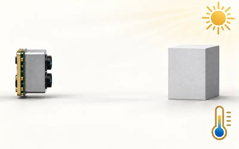
Both approaches actively illuminate the target and can support depth sensing in darkness, where visible scene texture is limited. Strong ambient light adds background signal; for structured light it can also reduce pattern contrast. Outdoor selection therefore needs a device specified and evaluated for the expected illumination, distance and target.
Dark surfaces may return little light at the operating wavelength. Glossy or transparent surfaces may redirect, saturate or transmit the illumination. With ToF, a return that has bounced between surfaces can bias the distance, a problem known as multipath. With structured light, poor pattern visibility or ambiguous correspondence can leave gaps or incorrect surface points. Surface handling varies by implementation; include the actual materials and recesses in the trial.
Integration and total system cost
Compare the finished system: camera, illumination, host processing, software, enclosure, calibration effort and mounting space. Structured-light geometry needs a stable calibrated arrangement; ToF also needs model-specific calibration and optical integration. An interface match does not establish API compatibility, matching timestamps or equal processing latency. A comparison based only on sensor price misses this work.
Which approach should you evaluate for your application?
Start with the task priority, then use the final column to plan the candidate evaluation. Each row connects an application to a sensing approach and the conditions that could change the choice.
| Application and priority | A useful starting point | What could change the choice? |
|---|---|---|
| AMR scene perception or people tracking | Evaluate area ToF when continuous depth coverage and update rate are central | Small obstacles, glossy floors, sunlight and latency may determine the required device; safety functions need a separate system assessment |
| Small-part inspection or reverse engineering | Evaluate industrial structured light for detailed stationary surface capture | A moving target needs a compatible acquisition method; reflective or recessed features need material and visibility trials |
| Robot bin picking | Start with structured light when grasping depends on fine geometry; include ToF when coarser object localization meets the task | Feature size, bin-wall reflections, occlusion and the robot cycle time decide whether the usable point cloud is sufficient |
| Parcel or pallet dimensioning | Include ToF for scene coverage; include structured light when edge and shape detail drive the tolerance | Conveyor speed, smallest parcel, black packaging and the required dimension error determine the final choice |
| Gesture or touchless interaction | Include ToF for body or hand depth; evaluate structured light when finer surface detail is needed | Finger size at the working distance, capture timing and host algorithm requirements matter more than the technology label |
| Sunlit outdoor depth sensing | Start with devices rated for the actual lighting conditions in either family | Useful range, target reflectance, optical filtering and mounting exposure must match the installation |
For example, a stationary molded-part inspection station can prioritize surface completeness and feature measurement, making structured light a sensible first evaluation. A mobile robot observing people usually starts with depth coverage and timely updates, making area ToF a sensible candidate. A conveyor measuring small packages combines both needs: test the complete dimension estimate while the package moves, including its edges and the background, rather than selecting from a still point-cloud image.
How to select and test
Define a measurable requirement: for example, valid depth at a stated distance, reflectance, illumination, motion speed, and field of view. Compare candidate systems with the same target set and report error distribution, missing-pixel rate, latency, and power. Security or biometric use also requires separate presentation-attack testing and a complete system assessment; a depth sensor alone does not establish authentication performance.
Use the application output as the acceptance test. For inspection, measure the smallest relevant feature against a reference. For dimensioning, compare the calculated object dimensions. For perception, include the smallest target and its motion through the viewing area. Record the camera mode, software version, acquisition settings and host so that the comparison can be repeated.
For a closer look at measurement checks, see our guides to ToF camera accuracy testing and RGB-D camera calibration and validation.
Prepare your depth sensor requirements
Share the following details when discussing a candidate sensor with our team. A sketch of the installation and a few representative target images can help explain the application.
- Application and output: describe the task and whether the host needs distance values, a depth map, or color and depth images.
- Working range and target: include the nearest and farthest distances, smallest target or feature, and typical surface materials.
- Viewing area: specify the scene width and height at the working distance, mounting position, and likely occlusions.
- Motion and timing: describe object speed, required update rate, and acceptable processing delay.
- Environment: include lighting, temperature, enclosure or cover window, and available mounting space.
- Host and connection: identify the processor, operating system, preferred interface, and power budget.
- Measurement acceptance: state the required error tolerance and valid-depth coverage under the intended conditions.
- Purchasing plan: include evaluation quantity, expected production volume, and project timing so we can discuss the next steps.
Explore DOMI ToF modules and RGB-D cameras
Our ToF camera modules provide a starting point for embedded depth-sensing projects. If your application uses both color and depth, explore our RGB-D cameras.
For a closer look at individual cameras, see the DM-RGBD5002A VGA ToF RGB-D Depth Camera and DM-RGBD5003A VGA ToF RGB-D Depth Camera. Compare each model's technical specifications and connection details with your host and installation requirements.
Tell us about your depth-sensing project. We can help you narrow the DOMI candidates around your working distance, target, viewing area and integration needs.