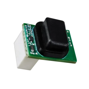

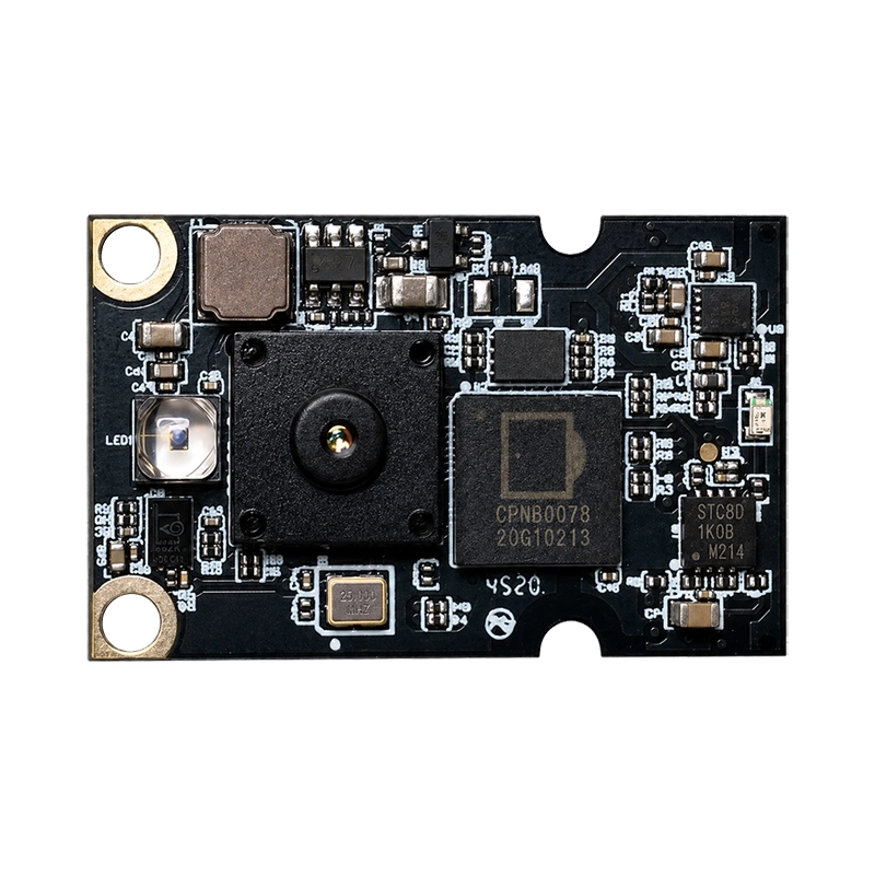
DMOS5030A/5031A 100 × 100 All-in-One 3D ToF Sensor Modules for IoT
DMOS5030A and DMOS5031A combine ToF sensing, VCSEL illumination and DM3602 processing on one board for embedded IoT products. Firmware-configurable output reaches 100 × 100 at up to 20 fps. Choose DMOS5030A for 0.2-4.8 m sensing with a 30° × 30° field of view, or DMOS5031A for 0.2-2.5 m sensing with 60° × 60° coverage.
Key Highlights
- Receive processed sensing results from a board that combines the ToF sensor, optics and DM3602 processor.
- Match coverage to the task with a narrower 850 nm version or a wider 940 nm version.
- Adapt resolution and update rate through firmware, with output up to 100 × 100 at 20 fps.
- Supply the module from a single 5 V rail and connect the host through the selected UART or SPI firmware mode.
Overview
The integrated Smart ToF ISP processes the sensor output, and an on-chip Cortex-M3 core runs application-specific algorithms before sending results to the host. This arrangement brings depth processing onto the sensing board for appliances, projectors and smart-space equipment.
The selected firmware defines the application output and host-interface mode. Processing functions include range finding, multi-zone human sensing, posture monitoring, gesture control and keystone correction. We can help match the required result type to the module and firmware configuration.
- Resolution
- 100 × 100
- Range
- 0.2-4.8 m / 0.2-2.5 m
- Field of View
- 30° × 30° / 60° × 60°
- Interface
- UART / SPI
Applications
Appliances and touchless interaction
Bring region sensing or gesture-related results into appliance controls through the selected firmware. Our HMI and smart-device guide explains the choice between proximity triggers and spatial input; the touchless gesture-control guide covers interaction-zone planning.
Projector geometry
Use the range-finding and keystone-correction application options in a projector or laser-TV architecture. Choose the optical version around the projection equipment’s distance and coverage requirements.
Presence and zone sensing
Multi-zone human sensing and posture-related processing provide inputs for smart lighting, automatic doors and indoor equipment. The host can use the selected application results to control its own events and operating states.
Technical specifications
| Parameter | Specification |
|---|---|
| Sensor | Global shutter; 100 × 100 array |
| Output resolution | Up to 100 × 100; firmware configurable |
| Frame rate | Up to 20 fps; firmware configurable |
| Processor | DM3602 with Smart ToF ISP and Cortex-M3 core |
| Host interface | UART or SPI; firmware configurable |
| Supply | 5 V; at least 500 mA supply capability at CN3 |
| Current consumption | Peak <500 mA; average <200 mA |
| Depth deviation | ≤2% in a darkroom with a target above 85% reflectivity |
| Board plan-view outline | 30.5 ±0.2 × 19 ±0.2 mm |
| Host connector | CN3; 12-pin, 0.5 mm pitch FPC on the back side |
| Module laser-safety classification | Class 1 |
Choose the optical version
| Selection point | DMOS5030A | DMOS5031A |
|---|---|---|
| Measurement range | 0.2-4.8 m | 0.2-2.5 m |
| Field of view | 30° horizontal × 30° vertical | 60° horizontal × 60° vertical |
| VCSEL wavelength | 850 nm | 940 nm |
| Sensing task | A defined region at longer distance | A wider region at near to mid-range |
Use the field of view and target distance together to plan the sensing region. Both versions share the DM3602 processing architecture, firmware-configurable host interface and single 5 V supply.
Host interface and integration
UART connection
UART uses 3.3 V CMOS signaling at 115200 bps, with 8 data bits, one stop bit, no parity and no flow control. RX receives configuration commands and TX sends processed results. The selected firmware defines the application data and command protocol.
CN3 connection groups
| Pin | Signal | Function |
|---|---|---|
| 1 | VCC_SYS | 5 V supply; at least 500 mA capability |
| 2 | GND | Ground |
| 3 | VDD_AP | Reserved; leave unconnected |
| 4-7 | SPI_MISO/SDA, SPI_CLK/SCL, SPI_CS, SPI_MOSI | Four-wire SPI; pins 4-5 also carry I2C multiplexing labels |
| 8 | AP_SYNC/AP_GPIO1 | Host strobe in slave mode or configurable GPIO |
| 9-10 | UART0_RX/AP_GPIO3, UART0_TX/AP_GPIO4 | UART or configurable GPIO |
| 11 | AP_GPIO2 | 3.3 V GPIO |
| 12 | AP_EN | Active-low enable; 0 powers on, 1 powers down |
Plan the FPC orientation, host signaling and optical clearance together. The module includes automatic laser shutdown during an abnormal condition. Include the installed optical arrangement in the finished product’s laser-safety assessment.
Technical resources
The DMOS5030A/5031A datasheet, v1.0 provides the architecture, connector definition and mechanical drawing.
FAQs
How do I choose between the two versions?
DMOS5030A offers 0.2-4.8 m sensing with 850 nm illumination and a 30° × 30° field of view. DMOS5031A offers 0.2-2.5 m sensing with 940 nm illumination and 60° × 60° coverage.
What processing takes place on the module?
The DM3602 ToF ISP processes sensor data, and its Cortex-M3 core runs the selected application algorithms. Processed results then pass to the host through the configured interface.
What host interfaces are available?
UART and four-wire SPI are firmware-configurable host modes. UART uses 115200 bps, 3.3 V CMOS signaling and an 8-N-1 frame. We can help choose the firmware and result format around the host’s task.
What are the resolution and frame-rate options?
Output is firmware configurable up to 100 × 100 at up to 20 fps. Select the resolution, timing and application output together.
What is the depth-deviation condition?
Depth deviation is ≤2% in a darkroom with a target above 85% reflectivity. Keep those conditions with the figure when using it as a reference for selection.
Discuss your embedded sensing task
Share the result your host needs, target distance, coverage region and preferred interface. We can help select the optical version and firmware configuration for your IoT device.
Need help integrating DMOS5030A/5031A?
Get expert guidance from our sensing engineers on product selection, evaluation samples, system integration, and technical requirements for your application.
You May Also Like
DM0301
DMS604