
DMP1KKM 905 nm 16-Channel Linear Pulsed VCSEL Array
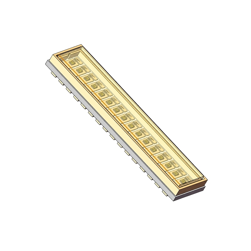
DMP1KKM provides a 16-channel linear VCSEL format for pulsed transmitter designs in a 17.3 × 4.0 × 1.7 mm AlN ceramic package. At 25 °C, each channel delivers 70 W typical and 40 W minimum peak optical power with a 15 A drive current, 1.5-2 ns pulse width and 0.03% duty cycle. Peak wavelength is 905 nm typical within a range of 895-915 nm at that test point.
Key Highlights
- Plan a segmented transmitter layout around a 16-channel linear emitter arrangement.
- Size the per-channel optical path using 70 W typical and 40 W minimum peak output at 25 °C, 15 A, 1.5-2 ns and 0.03% duty cycle.
- Match the receiver optics around a 905 nm typical wavelength and 3.0 nm maximum spectral bandwidth at the stated test point.
- Fit the array into a compact transmitter using a 17.3 × 4.0 × 1.7 mm AlN ceramic package.
Overview
DMP1KKM brings a linear array of pulsed emitters to LiDAR, surveillance and machine-vision transmitter architectures. The package drawing, recommended PCB pad pattern and numbered channel circuit diagram support electrical and mechanical layout planning.
The electro-optical characteristics describe each channel at a defined pulse condition. At 25 °C, 15 A, 1.5-2 ns and 0.03% duty cycle, forward voltage is 20.5 V typical and slope efficiency is 4.9 W/A typical. Use those figures with the per-channel optical output when assessing the emitter and driver.
- Channels
- 16-channel linear array
- Peak Wavelength
- 905 nm typ. (895-915 nm)
- Peak Power
- 70 W typ. / 40 W min. per channel
- Package
- 17.3 × 4.0 × 1.7 mm AlN
Applications
LiDAR transmitters
Use the linear channel arrangement as an emitter input for a pulsed LiDAR transmitter. Wavelength, per-channel output and beam divergence help define the source alongside the receiver, driver and transmitter optics.
Surveillance illumination
The 895-915 nm peak-wavelength range and 3.0 nm maximum spectral bandwidth provide inputs for a pulsed near-infrared illumination design. Match the emitter spectrum and coverage to the receiving equipment.
Machine-vision illumination
The linear format supports layout planning for spatially segmented illumination. Select the channel drive pattern, optics and acquisition timing around the scene your vision system needs to observe.
Technical specifications
Per-channel electro-optical characteristics
All values below apply to each channel at T = 25 °C. The optical, voltage, divergence, bandwidth, slope-efficiency and resistance test point is If = 15 A, pulse width 1.5-2 ns and duty cycle 0.03%.
| Parameter | Minimum | Typical | Maximum | Unit |
|---|---|---|---|---|
| Peak wavelength | 895 | 905 | 915 | nm |
| Peak optical power | 40 | 70 | W | |
| Forward voltage | 20.5 | 30 | V | |
| Beam divergence, FW D86 | 24 | ° | ||
| Spectral bandwidth | 3.0 | nm | ||
| Slope efficiency | 4.9 | W/A | ||
| Series resistance | 0.7-0.9 | Ω |
At 25 °C with 1.5-2 ns pulses and 0.03% duty cycle, operating current is 15 A typical and threshold current is 0.4 A typical. FW D86 is the full angular width containing 86% of the emitted optical power.
Absolute maximum ratings
These are device stress limits. Select the operating pulse train and driver around the intended electrical and thermal design.
| Parameter | Rating | Condition |
|---|---|---|
| Operating temperature | -20 to 85 °C | Absolute maximum rating |
| Storage temperature | -40 to 110 °C | Absolute maximum rating |
| Pulsed forward current | 30 A per channel | Tp = 2.0 ns; DC = 0.03%; Ts = 25 °C |
| ESD withstand voltage | 4 kV | Human Body Model |
| Soldering temperature | 260 °C | Absolute maximum rating |
| Reverse breakdown voltage | 50 V | Absolute maximum rating |
Package and assembly
The AlN ceramic body measures 17.3 × 4.0 × 1.7 mm, with a general drawing tolerance of ±0.2 mm. Use the recommended pad pattern and the circuit diagram’s channel numbering for PCB layout. Coordinate the driver routing, optical arrangement and thermal path during transmitter development.
Pb-free SnAgCu reflow profile
| Profile feature | Requirement |
|---|---|
| Preheat / soak | 150-200 °C for 60-120 s |
| Ramp-up rate | 3 °C/s maximum |
| Liquidus temperature / time above | 217 °C / 60-150 s |
| Peak package-body temperature | 260 °C |
| Time within 5 °C of peak | 30 s |
| Ramp-down rate | 6 °C/s maximum |
| Time from 25 °C to peak | 8 min maximum |
Use ESD-controlled handling and protect the drive circuit against electrical overstress and surge current. Ground personnel and equipment, with suitable antistatic and ionization measures in the assembly environment.
Technical resources
The DMP1KKM product specification, Rev. 1.0 includes the per-channel characteristics, package outline, pad pattern, circuit diagram and assembly profile.
FAQs
What does the 70 W peak-power value describe?
It is the typical peak optical output of each channel at 25 °C, 15 A, a 1.5-2 ns pulse width and 0.03% duty cycle. Minimum peak power at that test point is 40 W per channel.
What optical figures should I use for receiver and transmitter planning?
At the stated per-channel test point, peak wavelength is 895-915 nm with a 905 nm typical value. Spectral bandwidth is 3.0 nm maximum, and beam divergence is 24° maximum using the full-width D86 definition.
What package and channel arrangement does DMP1KKM use?
The emitter uses a 16-channel linear arrangement in a 17.3 × 4.0 × 1.7 mm AlN ceramic package. The drawing provides a recommended pad pattern and a circuit diagram numbered by channel.
What assembly guidance is available?
The product specification provides a Pb-free SnAgCu reflow profile with a 260 °C peak package-body temperature. Use ESD-controlled handling, grounding and surge protection during assembly and integration.
Discuss your pulsed-array transmitter
Share the illumination region, receiver wavelength, channel drive pattern and available PCB space. We can help evaluate DMP1KKM around your optical layout, pulse conditions and laser-safety assessment.
Need help integrating DMP1KKM?
Get expert guidance from our sensing engineers on product selection, evaluation samples, system integration, and technical requirements for your application.
You May Also Like
DMP300KP
DMP200W