
DMP20S 405 nm TO56 Violet Laser Diode Module
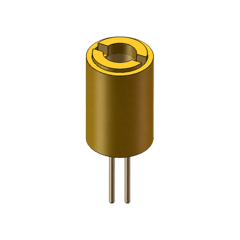
DMP20S combines a 405 nm violet laser and monitor photodiode in a compact TO56 CAN package. It provides 18 mW typical CW optical output at 40 mA and Tc = 25 °C, with separate laser and monitor connections for integration into your driver and optical assembly.
Key Highlights
- Add a violet light source to your optical assembly with 405 nm typical emission at the stated CW test point.
- Plan the optical-output requirement around 18 mW typical at 40 mA and Tc = 25 °C.
- Bring a monitor signal into an external feedback design using the integrated photodiode.
- Connect the laser, monitor photodiode and common case node through the three-pin TO56 package.
Overview
DMP20S provides a compact CW laser source for violet laser modules and OEM optical assemblies. At 40 mA and a case temperature of 25 °C, peak wavelength is 405 nm typical within a 400–410 nm range, and optical output is 18 mW typical.
The package includes a monitor photodiode with a typical monitor current of 0.2 mA at the same operating point. Its separate PD connection lets you bring the monitor signal into external driver and feedback electronics.
The TO56 CAN body is 5.90 mm in diameter. A three-pin interface provides the photodiode, case-connected common node and laser connections, giving your electronics access to both the source and its monitor signal.
- Peak Wavelength
- 405 nm typ. (40 mA CW, Tc = 25 °C)
- Optical Output
- 18 mW typ. (40 mA CW, Tc = 25 °C)
- Package
- TO56 CAN; 3-pin LD / PD interface
- Monitor Current
- 0.2 mA typ. (40 mA CW, Tc = 25 °C)
Applications
Violet laser modules
Integrate a 405 nm CW source into a laser module or optical assembly. Plan the driver, mounting and optics around the required power, wavelength and beam at the working plane.
External optical-feedback designs
Use the monitor photodiode signal as an input to external feedback electronics. Characterize the relationship between monitor current and optical output within your driver and temperature-control arrangement.
Technical Specifications
Electro-optical characteristics
The optical-output, wavelength, voltage, slope-efficiency, beam-divergence and monitor-current values below apply at If = 40 mA, CW and Tc = 25 °C.
| Parameter | Minimum | Typical | Maximum |
|---|---|---|---|
| Peak wavelength | 400 nm | 405 nm | 410 nm |
| Optical output | — | 18 mW | — |
| Operating voltage | — | 4.8 V | 5.6 V |
| Slope efficiency | — | 1.0 W/A | — |
| Beam divergence, D86 | — | 3° | — |
| Monitor current | 0.1 mA | 0.2 mA | 0.5 mA |
| Threshold current | — | 15 mA | — |
Threshold current is a separate characteristic. A dash indicates an unassigned Min, Typ or Max entry.
Absolute Maximum Ratings
| Parameter | Rating |
|---|---|
| Operating case temperature | −20 °C to +70 °C |
| Storage temperature | −40 °C to +85 °C |
| Maximum reverse voltage | 2 V |
| Soldering temperature and exposure | 260 °C for less than 5 s |
Use the electro-optical operating point above for output selection and the absolute maximum ratings for stress-limit checks.
Package and Pinout
| Mechanical item | Dimension |
|---|---|
| Package | TO56 CAN |
| Body diameter | 5.90 ±0.1 mm |
| Body height, excluding leads | 8.80 mm; drawing tolerance ±1 mm |
| Lead diameter | 0.45 ±0.1 mm |
| Unmarked drawing tolerances | ±0.1 mm |
Three-pin connection, bottom view
| Pin | Label | Connection |
|---|---|---|
| 1 | PD | Monitor photodiode anode |
| 2 | CASE | Case-connected common cathode node |
| 3 | LD | Laser diode anode |
Use the bottom-view package drawing to orient the pins before connecting the driver and monitor circuit.
Integration
Driver and monitor connection
Use a current-regulated laser driver with surge protection. Plan startup, shutdown and fault behavior around the laser connection, and match the external monitor circuit to the photodiode polarity and operating point.
Thermal design and handling
Provide a thermal path from the package and include case temperature in optical-output measurements. The 18 mW typical output is characterized at Tc = 25 °C.
Follow grounded, ESD-controlled handling practices and the specified soldering temperature and exposure limit. Include beam access, reflections, shielding and laser-safety review in the optical assembly design.
FAQs
Under what conditions is the 18 mW optical output specified?
DMP20S provides 18 mW typical CW optical output at a forward current of 40 mA and a case temperature of 25 °C.
What wavelength does DMP20S provide?
Peak wavelength is 405 nm typical, with a 400–410 nm minimum-to-maximum range at If = 40 mA, CW and Tc = 25 °C.
How can I use the monitor photodiode?
The PD connection provides a monitor signal for external electronics. Monitor current is 0.1–0.5 mA, with a typical value of 0.2 mA, at If = 40 mA, CW and Tc = 25 °C. Design the external feedback circuit around the PD polarity and measured monitor-to-output relationship.
What is the three-pin connection?
In the bottom view, pin 1 is the photodiode anode, pin 2 is the case-connected common cathode node, and pin 3 is the laser diode anode. Use the package drawing to establish orientation in your assembly.
Technical Resources and OEM Enquiries
Download the DMP20S specification, Rev. 1.1, 6 March 2023.
Tell us your wavelength and output requirements, driver arrangement, working temperature and package constraints, together with the evaluation quantity and project schedule. We can discuss DMP20S for your optical assembly. Contact DOMI about DMP20S.
Need help integrating DMP20S?
Get expert guidance from our sensing engineers on product selection, evaluation samples, system integration, and technical requirements for your application.
You May Also Like
DMP1KKM
DMP300KP