

Choose the wavelength and operating mode
Pulsed sensing and continuous optical delivery place different demands on the emitter, driver and thermal design. Compare the required wavelength, channel arrangement and output conditions before selecting a package.
| VCSEL product | Wavelength and format | Optical output and test conditions | Selection focus |
|---|---|---|---|
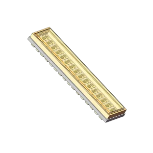
| DMP1KKM | 905 nm typical, 895-915 nm; 16-channel linear pulsed array | 70 W typical / 40 W minimum peak power per channel at T = 25 °C, If = 15 A, 1.5-2 ns pulse width and 0.03% duty cycle | A channel-based illumination architecture for LiDAR or machine-vision evaluation |
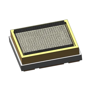
| DMP300KP | 905 nm typical, 895-915 nm; pulsed VCSEL emitter | 300 W typical device optical output at Ts = 25 °C, IF = 61 A, 5 ns pulse width and 0.025% duty cycle | Pulsed ToF or 3D-sensing emitter selection around the required drive and optical geometry |
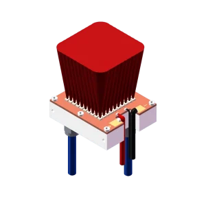
| DMP200W | 980 nm; water-cooled CW VCSEL module | 200 W and 30 W CW operating points at Tc = 25 °C; cooling water at 15-25 °C and at least 10 L/min | Continuous optical delivery for laser heating and surface-process development |
DMP1KKM's power values apply to each channel. DMP300KP's output applies to the emitter under its specified pulse conditions. DMP200W's CW operating points describe continuous optical delivery. Keep these power definitions with the values throughout driver, optical and thermal design.
405 nm CW laser source
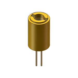
DMP20S provides 18 mW typical CW output at If = 40 mA and Tc = 25 °C, with a 405 nm typical peak wavelength. Its TO56 CAN package includes a monitor photodiode for external feedback evaluation. Use this laser-diode route when the optical design calls for a 405 nm source, and review its own electrical, optical and package specifications.
Match the emitter to the complete optical design
For pulsed sensing, work from the required pulse width and repetition pattern, peak current, receiver wavelength response and illumination geometry. DMP1KKM provides a linear channel arrangement; DMP300KP provides a separate pulsed-emitter route. The driver and optics determine how that output reaches the target.
For CW equipment, plan the required delivered power and spot at the working distance together with electrical supply and cooling. DMP200W's water temperature and flow requirements are part of its operating conditions. Its separate 30 W and 200 W characterization points should each be read with their corresponding electrical values.
Package dimensions, mounting, heat transfer and the final beam path also shape the selection. Component optical output is one input to system design; delivered illumination and application performance are evaluated in the assembled equipment.
FAQs
How should I compare pulsed and CW power specifications?
Read pulsed peak power together with pulse width, duty cycle, drive current and test temperature. Read CW output with its drive and cooling conditions. For an array, keep the per-channel rating distinct from an output specified for a complete emitter or module.
Which details help shortlist a VCSEL product?
Share the wavelength window, required optical output, operating mode, pulse pattern where relevant, and working distance. Channel arrangement, beam requirements, package limits and available cooling help us compare the hardware routes.
Discuss your optical-source requirements
Send your intended application, optical output and operating conditions, together with driver, mounting and cooling constraints. We can help identify a candidate product and the specifications needed for your evaluation.