

Choose the sensing route for your task
| Sensing task | Product route | Selection focus |
|---|---|---|
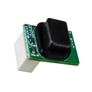
| Compact approach detection or local distance input | DM0301 | Single-zone measurement in a 4.40 × 2.40 × 1.00 mm optical LGA; I2C host control |
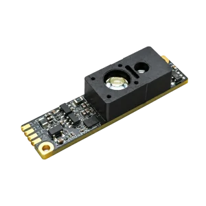
| Short-range proximity through a small module | DM-DTOF2002C0 | 2–120 cm with a white-card target; I2C / UART; 10 × 8 × 7.6 mm module |
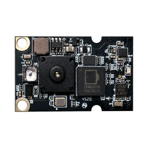
| Spatial distance samples across a region | DMOS5030A/5031A | Up to 100 × 100 output; select distance and coverage by variant |
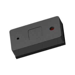
| Directional measurement over a longer distance | DMS604 | Narrow ≤1.3° field of view; UART distance output; indoor and bright outdoor specifications |
A single-point sensor provides distance information along its sensing direction. An area sensor supplies spatial samples across a region, allowing your host application to use target position and scene geometry. Use the target size, mounting direction and coverage requirement to choose the route.
Compare distance, coverage and host interfaces
| Model | Distance specification | Field of view | Host interface |
|---|---|---|---|
| DM0301 | Indoor ranging up to 4,000 mm; nominal configurable range 20 mm–5 m | 25° | I2C, 7-bit address 0x41, up to 1 Mbit/s |
| DM-DTOF2002C0 | 2–120 cm with a white-card target | 25° | I2C / UART |
| DMOS5030A | 0.2–4.8 m | 30° H × 30° V | UART / SPI, firmware configurable |
| DMOS5031A | 0.2–2.5 m | 60° H × 60° V | UART / SPI, firmware configurable |
| DMS604 | Typical limits: 58 m indoors; 35 m outdoors at 100 klux; both with 18%–88% target reflectivity | ≤1.3° | UART |
The DMOS variants share output up to 100 × 100 and refresh rates up to 20 fps, configurable in firmware. DMOS5030A uses 850 nm illumination for its longer-range, narrower-coverage configuration; DMOS5031A uses 940 nm illumination for its wider-coverage configuration.
Distance limits describe the stated model and conditions. DM0301's indoor distance specification and nominal configurable range are separate values. Match target reflectivity, ambient light, update timing and the optical assembly to the sensing task when planning the operating point.
Plan electrical and host integration
I2C for compact proximity designs
DM0301 uses a 2.97–3.63 V supply, with 3.3 V typical, I2C control, XSHUT and GPIO1 data-ready signaling. Plan its startup and firmware sequence, distance-result handling and cover-glass calibration with the host driver. For an existing ST board, our VL53L4CD replacement guide connects the hardware replacement position with supply, software and optical migration work.
DM-DTOF2002C0 combines a sensor and onboard MCU in a four-pin module, with a 3.0–3.6 V supply and I2C / UART control. Its 36 ms working cycle provides a timing reference for a short-range proximity input. Match the module connection and command format to your host acquisition layer.
UART or SPI for area sensing
DMOS5030A/5031A use a 5 V input and a 12-pin FPC host connector. Their firmware-configurable interface routes support host planning around the selected mode, output resolution and refresh rate. The v1.0 UART configuration is 115200 bps with 3.3 V CMOS signaling, 8 data bits, one stop bit and no parity. Coordinate the firmware and protocol configuration with us for the interface your design uses.
UART for directional long-range measurement
DMS604 combines 905 nm illumination, ranging processing and UART output with a 5 V supply. Plan the target area and mechanical alignment around its narrow field of view, and include window transmission and application timing in the integration review.
Connect sensor selection to the application
For local robot distance channels, use the robotics and AMR guide to define the sensing position and response time. For airborne distance sensing, our UAV selection guide explains single-point and area routes, attitude, illumination and host timing. For interaction zones and spatial gesture processing, see touchless gesture control.
When your application needs a denser depth image or an embedded MIPI pipeline, explore our ToF camera module selection. For color with VGA depth over USB, use our RGB-D camera guide.
Technical resources
The DMOS5030A/5031A datasheet, v1.0 includes variant specifications, the FPC pinout and UART settings. Each linked product page provides its model-specific specifications and integration information. Share the intended host and interface with us to discuss the documentation and configuration for your design.
Frequently asked questions
Which ToF sensors should I consider for short-range proximity?
DM0301 provides single-zone ranging in a compact optical LGA with I2C control. DM-DTOF2002C0 provides a small sensor module with I2C / UART and a 2–120 cm white-card distance specification. Compare target distance, package, supply and host integration for your device.
How do I choose between DMOS5030A and DMOS5031A?
DMOS5030A combines a 0.2–4.8 m range with a 30° × 30° field of view and 850 nm illumination. DMOS5031A combines a 0.2–2.5 m range with a 60° × 60° field of view and 940 nm illumination. Choose the variant around the working distance, region coverage and target geometry.
Which sensor provides long-distance directional ranging?
DMS604 provides UART distance output with a ≤1.3° field of view. Its typical distance limits are 58 m indoors and 35 m outdoors at 100 klux, both specified with 18%–88% target reflectivity. Use these conditions when planning your target and mounting arrangement.
Discuss your sensing requirements
Share your sensing task, target distances and materials, lighting, required update timing, host interface and mechanical constraints. Discuss your ToF sensor application with our team so we can help select a model and evaluation approach.