Time-of-Flight depth sensing can provide distance information for robot obstacle perception, pallet docking and near-field interaction. Select a sensor from the smallest relevant target, working distance, coverage, motion and host processing requirements.
We offer area dToF modules, MIPI depth modules and USB RGB-D cameras for robot development. Choose area distance sensing, embedded depth or combined color and depth to match your perception task and host design.
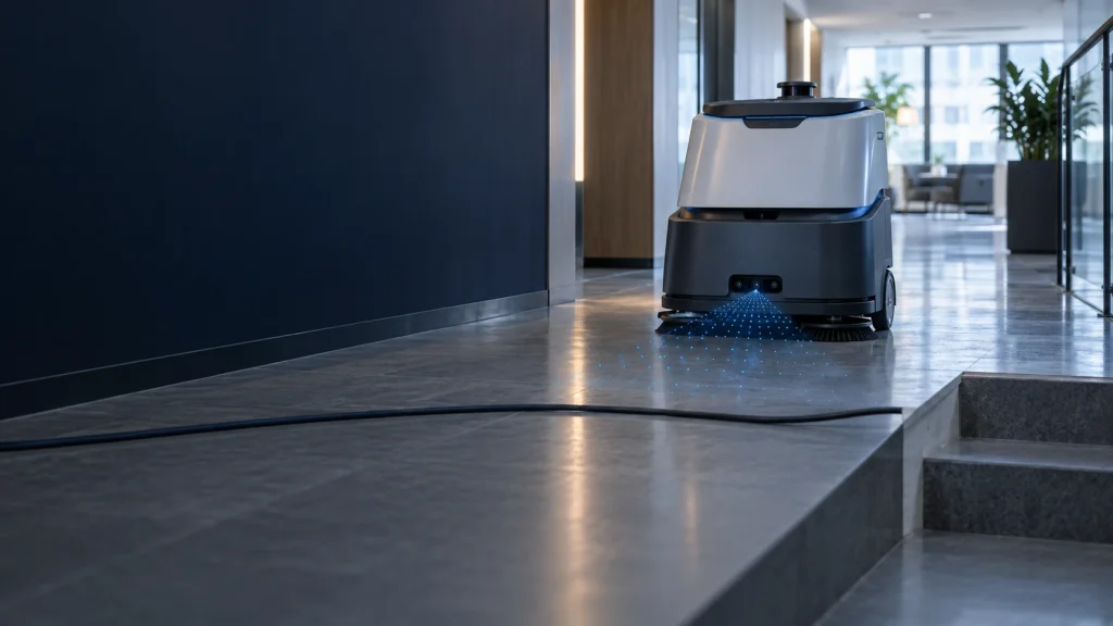
Add 3D ToF or RGB-D depth sensing to cleaning and delivery robots for near-field obstacle, overhang and drop-off perception. Compare camera options, mounting geometry and validation methods for integration with the robot’s navigation system.
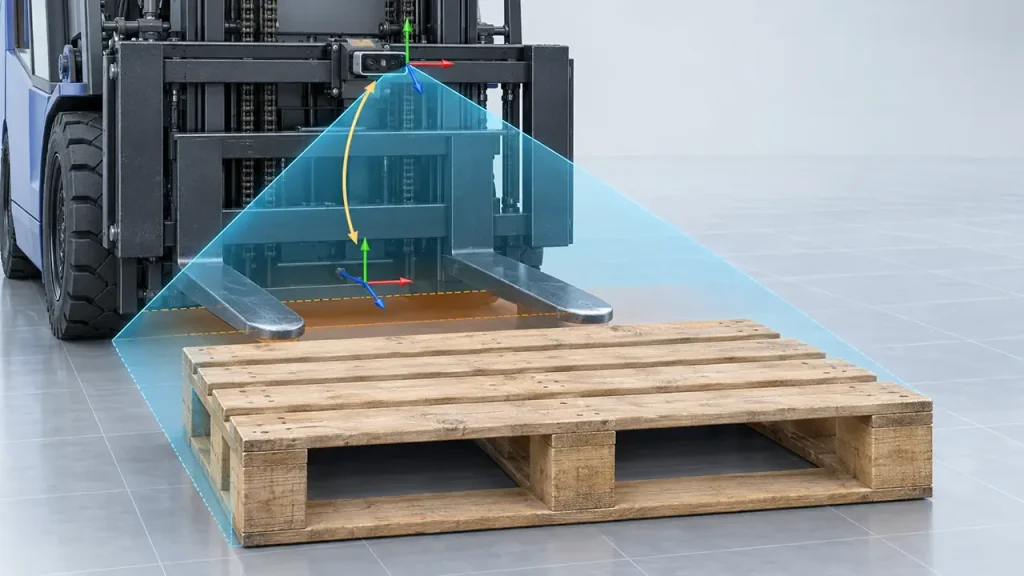
Provide autonomous forklifts with 3D depth data for pallet pose estimation, fork-pocket localization and docking alignment. Explore camera selection, mounting and validation requirements for integrating depth sensing into the vehicle’s perception and control loop.
Use these hardware routes to plan sensor placement, perception processing and control integration around your robot task.
Compare depth hardware
DMAS2M001 provides a 40 × 30 depth array at 10 fps, with a 0.2–8 m range at 30 klux and 10%–90% target reflectivity. See the robot and UAV evaluation guide for temporal sampling and integration questions.
USB RGB-D cameras provide VGA depth and color imaging for applications that require both streams. Plan calibration, frame timing and software integration around your robot host.
ToF camera modules include board-level MIPI options for an embedded host design. Evaluate the full processing pipeline, driver support and supply requirements alongside the optical specifications.
For a separate point measurement, review DM0301. A single-point device covers a different measurement task from an area depth camera.
Define a robot evaluation
Record the required near and far distances, smallest relevant object, mounting height and tilt, robot motion and allowable response time. Test the materials and lighting found at the intended site, including dark surfaces, reflective packaging, narrow targets and occlusion where applicable.
Measure object detection behavior, valid data coverage, measurement error and end-to-end latency separately. Define the system response to missing, delayed or low-confidence depth. Where the robot has safety-related requirements, evaluate the complete sensing and control architecture against those requirements.
FAQs
Which ToF camera is suitable for an AMR?
Select from a specific task and operating envelope. Area obstacle sensing, color-assisted perception and detailed docking geometry use resolution, frame timing and integration routes matched to the task.
How should I choose resolution for obstacle perception?
Match spatial sampling to the smallest relevant object and its distance from the camera. Include field of view, mounting and processing time to select a configuration for the required detection zone.
What should I provide for a camera recommendation?
Share the task, distance envelope, smallest target, speed, mounting location, lighting, host platform and acceptance criteria. Include representative scene images or object dimensions when available.