
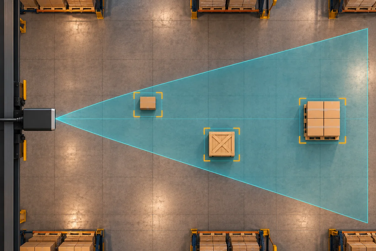
Choosing a ToF camera for robotics starts with the decision the robot must make from depth data. Define the nearest and farthest targets, the area the camera must cover, the smallest relevant feature, how the scene can move, and what the host system needs to receive. Only then should you compare camera formats and model specifications.
Compare specifications under their stated operating conditions. Target material, reflectivity, angle, ambient light, optical installation, acquisition mode, and processing can all affect the depth data the robot receives. Use the product documentation to screen candidates, then test the shortlist on the installed robot.
Start with the robot task, not a camera ranking
Describe the target and the robot decision before creating a shortlist. Locating a pallet opening, measuring a package, detecting an obstacle, and estimating the position of a part do not require the same coverage, spatial detail, timing, or output.
Use a requirements worksheet that keeps the task and its test conditions together:
| Project question | Selection requirement to define |
|---|---|
| What object, surface, opening, or region must be measured? | Target classes, materials, reflectivity, geometry, angle, and minimum relevant feature |
| What is the nearest required target? | Minimum working distance, mounting position, and near-field blind area |
| What is the farthest required target? | Required distance envelope under the intended target and ambient-light conditions |
| How wide and tall is the required scene? | Horizontal and vertical coverage at the nearest and farthest working distances |
| What is the smallest feature the software must use? | Required target sampling and boundary quality at distance |
| How can the robot or target move? | Required update rate and end-to-end timing budget |
| What must the camera provide? | Single distance, an array of distances, a depth map, IR data, RGB plus depth, or a point cloud |
| Where will processing run? | Camera, embedded host, or external computer; data-path and compute requirements |
| What mechanical constraints apply? | Mounting height, angle, envelope, optical clearance, protective window, and service access |
| What must pass before the design is accepted? | Test targets, distances, light states, motion cases, invalid-data handling, and acceptance measures |
The worksheet gives engineering, product, and sourcing teams a common basis for comparing candidate formats.
Choose the required depth output and camera format
The output needed by the robot helps determine whether the project should begin with a single-point sensor, an area-depth module, a complete USB depth camera, or an RGB-D camera.
Single distance or range zones
If the application needs one distance or a small number of range zones, start with the ToF sensor selection guide.
Area depth in an embedded design
An embedded area-depth module can suit a product in which the robotics team controls the mechanical design, host electronics, data path, and processing architecture. Before choosing this route, define the required interface, processing location, calibration handling, optical clearance, and enclosure design.
Complete USB depth camera
For a complete USB depth camera, plan around the available outputs, USB mode, host data rate, calibration, mounting, and application processing.
RGB-D camera
Choose RGB-D when the application needs both color and depth. Decide whether you need separate streams or aligned data, then plan calibration and the transform into robot coordinates. Explore camera families in the RGB-D camera category.
Set the working range and minimum range
Define the nearest and farthest positions where the robot needs usable depth. Screen candidate working ranges against the project’s target and ambient-light conditions.
A bright, flat reference target can produce different depth data from dark packaging, angled metal, a narrow edge, a transparent surface, or a small object against a distant background. Compare maximum-range values directly only when target, light, optical configuration, and acquisition mode are comparable. Note any unspecified test conditions so the comparison can be validated under equivalent conditions.
Check near-field coverage from the planned mounting position. Use the optical axis, robot bodywork, and required floor or target coverage to identify gaps, even if the camera reaches the far end of the scene.
If sunlight, temperature, or an outdoor enclosure drives the selection, see the outdoor ToF camera evaluation guide.
Calculate field of view and target sampling
Field of view describes an angle. Robotics software works with targets and regions that occupy physical space. Convert the camera’s documented horizontal and vertical fields of view into coverage at the required distances, then estimate how many depth samples fall on the smallest relevant target.
For an ideal rectilinear view of a plane perpendicular to the optical axis, horizontal coverage can be estimated as:
coverage width = 2 × distance × tan(horizontal FOV ÷ 2)
Use vertical FOV for coverage height and horizontal FOV for width. For distorted optics, tilted surfaces, or precise edge locations, use the applicable camera calibration.
Estimate sampling density from the physical coverage and the number of depth samples along the corresponding axis. Use the estimate to screen the smallest relevant feature, then test how much usable depth remains when invalid returns, mixed pixels, target boundaries, angle, filtering, and calibration affect the measurement.
Check coverage at the nearest and farthest working distances
Calculate coverage at both ends of the distance envelope. A field of view that captures the full scene at the far distance may include excessive background or insufficient target sampling. A narrower view may improve sampling on the target but miss required regions or become sensitive to mounting tolerance.
Check the installed view for obstructions from the robot body, mounting bracket, protective window, or other hardware.
Separate resolution, accuracy, and repeatability
Each term answers a different measurement question.
- Spatial resolution describes the number or arrangement of sampled positions in the depth image. It influences target sampling but does not establish measurement accuracy.
- Depth resolution can refer to depth quantization or the smallest distinguishable depth change. Use the definition given by the applicable product document or test method.
- Accuracy describes how close a measured value is to an accepted reference under stated conditions.
- Repeatability or precision describes how measurements vary when the same condition is repeated. Consistent measurements can still contain bias.
A higher pixel count does not automatically produce better accuracy. Optics, illumination, target return, calibration, acquisition settings, invalid-data handling, and processing can all affect the result. For robotics, ToF camera resolution, accuracy, and frame rate should be evaluated in the same documented operating mode rather than as isolated headline values.
Match frame rate and timing to robot motion
Frame rate describes how often frames are produced in a documented mode. It is not the same as end-to-end latency. A robotics timing budget may include exposure or integration, sensor readout, on-device processing, transport, host processing, coordinate transformation, application logic, and the robot control cycle.
Start with the motion case:
- Define the maximum relevant robot and target motion.
- Define how much movement between usable depth updates the application can tolerate.
- Identify the documented frame mode and output used for evaluation.
- Measure the installed path from acquisition through the application decision.
- Record missing, delayed, repeated, or invalid frames explicitly.
Compare the resolution and frame rate supported together in the operating mode the application will use.
Test target materials and operating conditions
Test shortlisted cameras with the targets the robot will encounter, including difficult materials, angles, and backgrounds relevant to the task.
| Test dimension | What to include | What to observe |
|---|---|---|
| Target material and return | Representative light, dark, reflective, transparent, low-return, or mixed-return targets where relevant | Valid and invalid depth behavior and boundary quality |
| Distance and angle | Near, nominal, and far positions; representative target angles | Coverage, usable target samples, missing returns, and measurement behavior |
| Ambient light | The light states expected at the installed location | Changes in valid-data behavior for the same target, distance, and camera mode |
| Motion | Static and representative moving cases | Frame behavior, missing frames, and application timing |
| Optical installation | Open setup and final protective window or enclosure, where applicable | Reflections, obscuration, contamination state, alignment, and changes in usable depth |
| Background and edges | Target against near and far backgrounds; narrow or boundary features | Mixed or invalid depth around edges and the effect on the application |
Use this matrix to define project-specific tests. Refer to the applicable product documentation for model-specific environmental limits and operating conditions.
Review the optical cover and installation
The receiver field of view and illumination footprint need to suit the same measurement area. For an embedded design, include lens clearance, emitter placement, alignment, and enclosure geometry in the mechanical review.
A protective window can reflect light back toward the receiver or change the received signal. Test with the final window material, coatings, spacing, angle, cleanliness, and enclosure. Assess outdoor suitability using the model’s documented conditions and installed-scene tests.
Plan interface, processing, and calibration
Check what the candidate device documents as its output: calculated depth, IR data, point cloud, RGB plus depth, or another data form. The host and software architecture depend on where depth is calculated and what additional processing the robot must perform.
For each candidate, document:
- Physical and electrical interface.
- Supported output formats and frame modes from the product documentation.
- Expected data rate in the selected mode.
- Processing location and host workload.
- Calibration storage and how calibration is applied.
- Representation of invalid or missing depth.
- Camera coordinates and the transform into robot coordinates.
- Startup, recovery, and data-quality checks required by the application.
MIPI CSI-2 and USB UVC describe different integration routes. Treat interface type and software compatibility as separate selection criteria. For the exact model and configuration, check driver, SDK, operating-system, host-platform, robotics-framework, synchronization, and multi-camera support.
Point-cloud output can reduce one processing step. Plan how the application will handle the coordinate frame, calibration, invalid data, and the transform into robot coordinates.
Compare relevant DOMI sensing routes
These models illustrate different sensing and integration architectures. Use the table to build a shortlist, consult the product pages for current specifications, and evaluate each candidate under the project’s operating conditions.
| DOMI model | Architecture represented | Key specifications and outputs | What to evaluate |
|---|---|---|---|
| DMAS2M001 | Compact area-depth route | 40 × 30 at 10 fps; 940 nm; 0.2–8 m at 30 klux for stated 10–90% reflective targets | Compare the stated ambient-light and target-reflectivity conditions with the installed scene |
| DMOM2808D | Embedded QVGA MIPI route | 320 × 240; 850 nm; two-lane MIPI CSI-2 | Match the distance envelope, frame mode, and host data path to the intended conditions |
| DMOM2508CL | Near-field embedded route | 320 × 240; 940 nm; two-lane MIPI CSI-2 | Compare the required near-field coverage and final optical installation before selection |
| DM5005A | Complete USB depth-camera route | QVGA; USB 2.0 UVC; 850 nm and 940 nm options; depth, IR, and point-cloud output | Test working distance and usable depth in the installed scene |
| DM-RGBD5002A | RGB plus depth route | Depth up to 640 × 480; RGB up to 1280 × 960; USB 2.0 | Check which depth and RGB modes are supported together for the project |
| DM-RGBD5003A | RGB-D evaluation route | VGA ToF depth; USB 2.0; point-cloud output | Use the model documentation to assess additional performance and integration requirements |
Once the robotics requirements are defined, compare DOMI ToF camera modules by sensing format and integration needs.
Validate the camera on the installed robot
Datasheet screening produces a shortlist. Installed-system validation determines whether the selected camera and configuration provide the data required by the robot.
Build the evaluation in stages:
- Record the configuration. Note the model, applicable product document, acquisition mode, and output used for the shortlist.
- Test representative targets across the distance envelope. Include the materials, sizes, angles, edges, backgrounds, and near-to-far positions that matter to the application.
- Test the installed scene. Include the intended ambient-light states, robot and target motion, and final optical installation.
- Inspect the data path. Record invalid depth, point-cloud or depth-map handling, calibration, coordinates, frame behavior, and application timing.
- Define project-specific acceptance and failure handling. State what the application does when depth is missing, uncertain, delayed, or outside the tested envelope.
An installed-system evaluation record should include:
| Record | Required content |
|---|---|
| Product identity | Exact model and applicable product document |
| Configuration | Resolution or output mode, frame mode, relevant settings, and processing path |
| Target | Material, reflectivity information where available, size, geometry, and angle |
| Scene | Distance, background, ambient-light condition, motion, and optical-window state |
| Output checks | Coverage, target samples, valid and invalid depth behavior, and the application-relevant measure |
| Timing checks | Acquisition and end-to-end timing measures defined by the project |
| Acceptance | Project-approved thresholds, failure behavior, and review owner |
For AMR-specific obstacle detection, navigation, and deployment considerations, see Depth Cameras for AMR Obstacle Detection and Navigation.
Turn your requirements into a shortlist
Complete the requirements worksheet before contacting DOMI. Include the robot task, target materials and size, nearest and farthest required distances, required scene coverage, motion case, light conditions, desired output, interface constraints, processing plan, and mounting sketch.
Share the worksheet through the DOMI contact page to discuss product formats and an evaluation path for your target, environment, configuration, and acceptance criteria.
Use the same worksheet to browse the ToF camera-module family or RGB-D camera family.
Robotics ToF camera selection FAQs
How do I choose the working range for a robotics ToF camera?
Start with the near and far limits of the robot's task. Screen product ranges against their stated target, light, and operating conditions. Then test shortlisted models with the intended materials, angles, light, optical installation, and acquisition mode.
How do FOV and resolution affect obstacle or target measurement?
Field of view determines physical coverage at a given distance. Spatial resolution determines how many sample positions are distributed across it. Use horizontal and vertical FOV to estimate how many samples fall on the smallest target, then test for usable depth at edges and boundaries.
Is a higher depth resolution always more accurate?
No. Spatial resolution, depth resolution, accuracy, and repeatability describe different properties. A higher pixel count can improve spatial sampling, but it does not by itself establish distance accuracy or repeatability. Compare those properties only under documented and compatible test conditions.
What frame rate is needed for a moving robot?
The required frame rate depends on robot speed, target motion, allowable movement between updates, exposure or integration behavior, transport, processing, and the control cycle. Define the end-to-end timing budget first, then evaluate the actual product mode and installed data path. Frame rate alone is not a latency specification.
How should a ToF camera be evaluated under ambient light and with reflective targets?
Test representative materials and angles at the required distances and ambient-light levels. Include dark, reflective, transparent, or mixed-return targets when the robot will encounter them. Record the camera mode, optical installation, valid and invalid depth, boundary quality, and the project's measurement method.
When should a robotics project use an embedded module, USB depth camera, or RGB-D camera?
Use an embedded module when the product architecture can support the electrical, optical, mechanical, processing, and calibration work. Consider a complete USB depth camera when its integration boundary fits the host and data path. Choose RGB-D when the application needs color and depth together. Compare each model's outputs, interface, calibration, processing, and compatibility against the integration plan.