
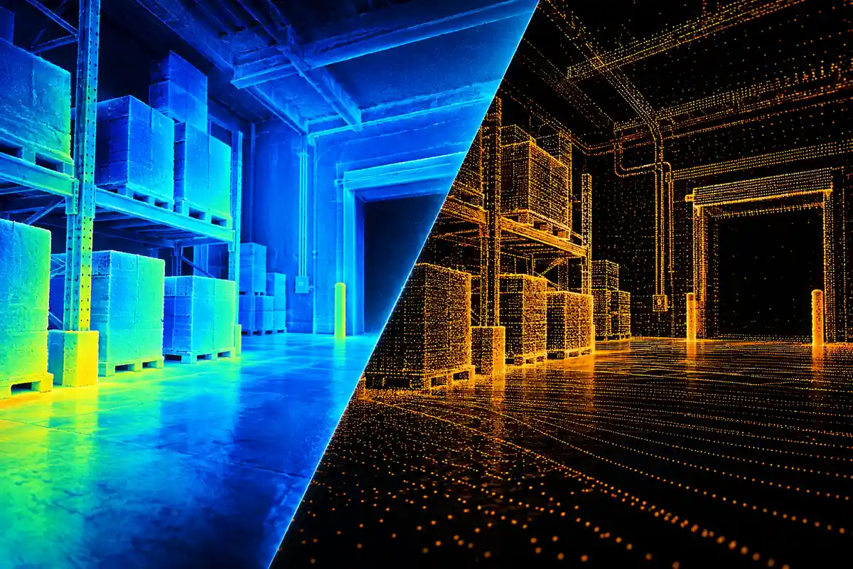
LiDAR and Time-of-Flight (ToF) are overlapping terms. LiDAR describes a light-based ranging system. ToF describes a way to estimate distance from light's travel time or phase delay. A pulsed LiDAR can therefore be a direct-ToF system, while some LiDAR architectures use other measurement methods, including frequency-modulated continuous wave (FMCW).
For an engineering project, the useful comparison is between specific sensing outputs and configurations. A single distance, a depth image and a scan of a larger space answer different questions. Choose the information your application needs, then compare the devices that can supply it.
Why the names are often confused
“ToF sensor” can mean a single-point rangefinder, a multi-zone receiver or a depth camera. “LiDAR” may describe a scanning instrument, a solid-state array or a complete system with optics and processing.
Both can use near-infrared laser illumination. Wavelength, optical power and eye-safety classification depend on the exact product and configuration. Those details belong in the device comparison, alongside the measurement architecture.
What should an engineer compare?
| Question | Relevant design choice | What to record during evaluation |
|---|---|---|
| How much space is measured? | One distance, several zones, a per-pixel depth image or a scanned point set | Target coverage, field of view, sample spacing and required region |
| How is distance estimated? | Direct pulse timing, phase measurement or another ranging architecture | Working interval, ambiguity handling and behavior when a return is invalid |
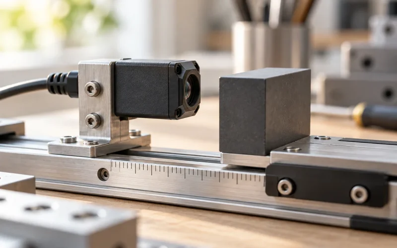
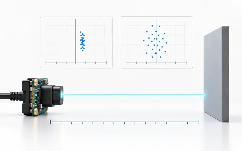
| How far and how accurately? | A specific device and acquisition configuration | Reference error, repeated-reading variation and valid returns under the same target conditions |
| How is motion sampled? | Frame acquisition or samples collected over a scan | Measurement timing, latency and target movement during acquisition |
| What is the integration cost? | Optics, mounting, calibration, interface, power and host processing | The complete data path and hardware needed for the application |
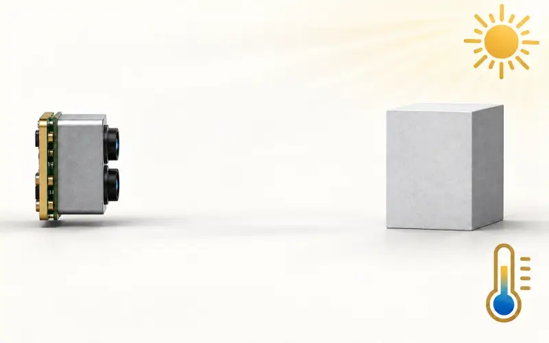
Use the same target reflectivity, ambient light, angle and error definition when comparing devices. If frame rate or acquisition settings differ, record the difference with the result.
ToF camera versus scanning LiDAR
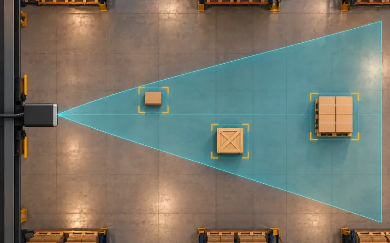
A ToF camera usually reports a depth value for many image locations within its field of view. A scanning LiDAR collects range samples across angles and produces a scan or point set. Both outputs can be converted into geometry for further processing, but their sampling patterns and acquisition timing can differ.
There are solid-state LiDAR designs and cameras with different illumination and receiver architectures. A useful comparison identifies the actual architecture and output, then tests the required scene. The labels alone do not establish a universal range, price or accuracy ranking.
Will the sampling pattern resolve a thin target?
Compare sample spacing at the target distance, not just the total number of points in a frame. As a hypothetical example, two scan rays separated by 1° have about 35 mm lateral separation at a 2 m plane near the forward axis. A 20 mm object can fall between such rays, depending on its position. These are chosen geometric inputs, not specifications for a particular LiDAR.
For an imaging camera, calculate the target footprint from field of view and image dimensions, then inspect valid depth on the object. For a scanning system, include angular spacing in both directions and the time at which each sample was collected. Moving the sensor or object during a scan changes the relationship between those samples. A dense-looking visualization after interpolation does not establish that the original measurement resolved the target. Use the field-of-view worked example to start the camera-side calculation.
Choose the output for your task
A presence detector may need only one range value. Locating an object within a working area may call for several zones or an array. Parcel measurement or manipulation may benefit from a calibrated depth image. Mapping a larger space may require a scan, a wider field of view or several sensing positions.
Our product routes provide different starting points:
- DM0301 provides a compact single-point I2C distance sensor for designs that use one range value.
- DMAS2M001 provides array depth, point-cloud and confidence outputs for spatial sensing across an area.
- DOMI RGB-D cameras combine color information with ToF depth sensing for projects that use appearance and geometry together.
Share the required coverage, target distance, output format and host platform with us to discuss an appropriate DOMI sensing route.
Evaluate the complete installation
Test the shortlisted devices on the target materials and angles found in the application. Include partly occluded objects, nearby backgrounds and representative sunlight and temperature. For moving targets, record measurement timing as well as distance error.
Keep valid-return rate, latency and power beside the range results. For a depth camera, inspect the required image region and the smallest target features your application must resolve. This gives the software team a clearer basis for deciding how the data will be used.
FAQs
Is LiDAR a type of ToF sensor?
Many LiDAR systems use time-of-flight ranging, so the terms overlap. LiDAR also includes architectures such as FMCW. ToF identifies a measurement method, while the device's optics, sampling arrangement and processing determine its coverage and outputs.
How does a ToF depth image differ from a LiDAR point cloud?
A depth image places distance samples on an image grid. A LiDAR scan or point cloud represents range samples at the instrument's sampling positions. A calibrated depth camera can also generate a point cloud, so compare the sampling geometry, timing and available data formats of the specific devices.
What should I compare for a robot sensing project?
Define the nearest and farthest targets, required coverage, smallest relevant objects, motion and host interface. Then evaluate distance error, usable returns, latency and power in that scene. Use the required output to shortlist a single-point sensor, an array, a depth camera or a scanning instrument.