
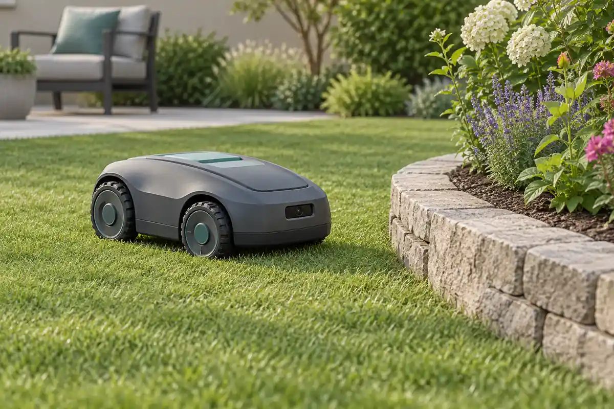
A robotic lawn mower can use depth measurements to observe nearby obstacles and terrain geometry. The useful sensing distance depends on the target, sunlight and installation, so an outdoor evaluation should reproduce the lawn conditions in which the mower must make decisions.
Define lawn and obstacle scenarios
List the objects the perception system must observe, including low objects, narrow supports, dark surfaces and objects partly hidden by grass. Specify their dimensions, approach directions and required decision distances. Separate obstacle observation from lawn-boundary interpretation, localization and cutting control.
A geometric return from a plant does not identify a lawn boundary by itself. Likewise, a clear camera view does not establish that a route is suitable for the mower. Map each measurement to the host function that uses it and the other sensors that function requires.
Test sunlight and low-reflectivity targets
Measure performance with the sun behind, beside and toward the sensor, and repeat tests in shadow and during lighting transitions. Record illuminance at the target, target reflectivity where known, exposure settings and valid-depth coverage. Lux alone does not describe all the spectral conditions affecting an infrared sensor.
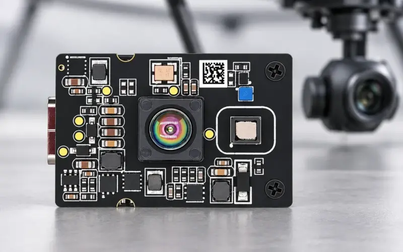
DMAS2M001 provides 40 × 30 depth sampling at 10 fps with a 60° × 45° field of view. Its specified 0.2–8 m range applies to 10%–90% reflectivity at 30 klux. Use those conditions as the starting reference, then test the actual lawn targets and illumination. DMOM2501C provides a 100 × 100 MIPI route with a 44° × 44° field of view for a different coverage and processing arrangement.
Mount for grass, slopes and near-field clearance
Draw the vertical field of view against the mower body, ground and required obstacle region. Check the nearest observable point, blade-deck occlusion and changes caused by climbing or descending a slope. Tall grass can conceal the lower part of an object and contribute returns of its own.
Transform depth into the mower coordinate frame using the installed camera pose. Recheck the transformation after mechanical adjustment. Account for chassis pitch and roll when comparing points with a ground model, rather than treating every raised return as the same obstacle.
Plan window, dust, water and cleaning
Select a cover material for the operating wavelength and evaluate it at the intended thickness and spacing. Keep emitted light from coupling directly into the receiver through the cover or enclosure. Include scratches, dust, grass residue and water droplets in tests of the assembled optical path.
Specify drainage, sealing, thermal management and cleaning for the complete installation. Window behavior and enclosure protection are separate from the depth module's nominal measurement range. Repeat measurements before and after cleaning to identify changes in the baseline.
Combine sensing and mower decisions
The camera supplies observations to the perception software. That software can filter points, identify relevant obstacle regions and update a local geometric map. Localization, route planning and motion control use their own state estimates and timing requirements. Validate the combined pipeline with the selected host, wheel sensing and other navigation inputs.
Measure the interval from capture to the controller receiving a usable result. Relate that latency to mower speed and the tested stopping or avoidance response. Frame rate alone does not describe the complete response time.
If comparing a scanning LiDAR and an area-depth camera, map their scan coverage, target samples and available motion compensation to the same obstacle scenarios. Either sensor still needs a defined path into the mower's localization, mapping or obstacle-processing software.
Record an outdoor evaluation matrix
| Variable | Useful test records |
|---|---|
| Light and material | Sun direction, illumination, target surface and valid-depth fraction |
| Lawn geometry | Grass height, slope, mounting pose and near-field clearance |
| Optical condition | Clean, dusty, wet and recently cleaned window |
| Moving operation | Target misses, false obstacles, timestamps and controller response |
Send us the mounting height, target matrix, outdoor conditions and host interface to discuss a development route. The robot-navigation guide covers the coordinate and timing pipeline; the robot-vacuum guide addresses indoor floor and low-obstacle tasks.
Discuss your evaluation with DOMI.
FAQs
What is the relevant sunlight specification for DMAS2M001?
The stated 0.2–8 m range is associated with 10%–90% target reflectivity at 30 klux. Evaluate other lighting and material conditions with the installed camera configuration.
Can depth measurements contribute to mower mapping?
They can provide local geometry to mapping software after calibration and coordinate transformation. The mapping and localization results also depend on pose estimation, timing and the navigation system.
Why test grass height and slopes?
Grass can hide targets and add returns, while slopes change the relationship between camera coordinates and the ground. Both affect the observed obstacle region and near-field clearance.
What should an outdoor evaluation include?
Include representative targets, sunlight directions, grass conditions, chassis motion and window contamination. Record valid measurements, perception errors and the resulting control-loop timing.