
ToF depth sensing gives a robot vacuum distance information across a selected area. It can support front-obstacle observation or a separate downward view of the floor. Start with the objects, floor transitions and available mounting space, then select the optical coverage and processing route for each task.
Separate front obstacles from downward cliffs
A front-facing depth module observes objects above the floor, including furniture legs and objects within its near-field coverage. A downward-facing sensor observes the expected floor surface. These views have different mounting angles, target distances and blind zones; one placement should not be assumed to cover both.
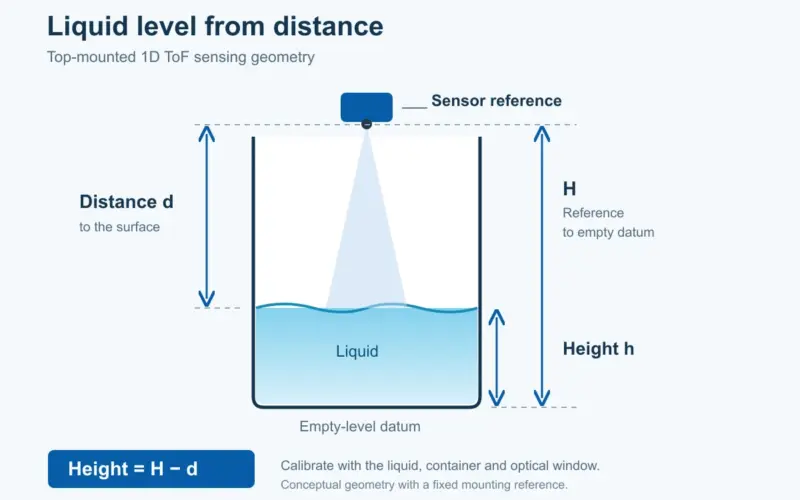
For a downward view, model the expected floor distance over the robot's pitch and roll range. A sudden increase in distance can be an input to a drop-detection algorithm. Missing returns also occur on dark or specular materials, so the controller needs an explicit unknown-data state. Define the response to an uncertain floor observation before testing stairs or platform edges.
Define small-object and floor targets
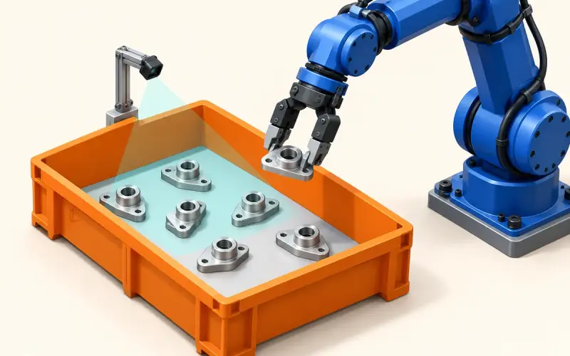
Specify the smallest relevant object, its height and width, the approach direction and the distance at which a decision is required. A low cable, a narrow chair leg and a broad wall occupy very different numbers of depth samples. Test the actual target set rather than using only a large white panel.
Use separate regions for floor support, low obstacles and taller objects. Record how pets, moving feet, rugs and objects partly hidden by furniture enter these regions. The host uses depth validity, geometry and temporal history to select a movement response; recognition and route planning belong to that processing pipeline.
Compare depth routes under matched conditions
| Route | Information used | Comparison conditions |
|---|---|---|
| Passive stereo | Corresponding features in two views | Texture, exposure, illumination, baseline and near-field coverage |
| Structured light | A projected pattern and its observed geometry | Pattern visibility, ambient light, reflectivity and projector-camera alignment |
| ToF | Travel-time-related optical measurements | Ambient light, return signal, mixed pixels, reflective paths and integration settings |
Compare complete configurations at the same distance, target size, lighting and motion. Include their optics, host processing, power and installation volume. Active illumination supports measurement in low visible light, while performance in sunlight still needs evaluation with the selected module and surfaces.
LiDAR describes a wider family of optical ranging systems. For a robot vacuum, compare a scanning unit's actual scan plane and angular samples with an area-depth camera's vertical and horizontal coverage. A horizontal scan used for mapping may need another view to observe an object below that plane. Select by the required geometry and software inputs rather than treating LiDAR and ToF as mutually exclusive labels.
Fit the optical head in the chassis
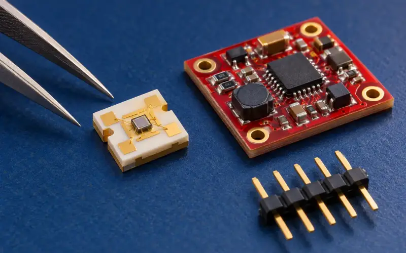
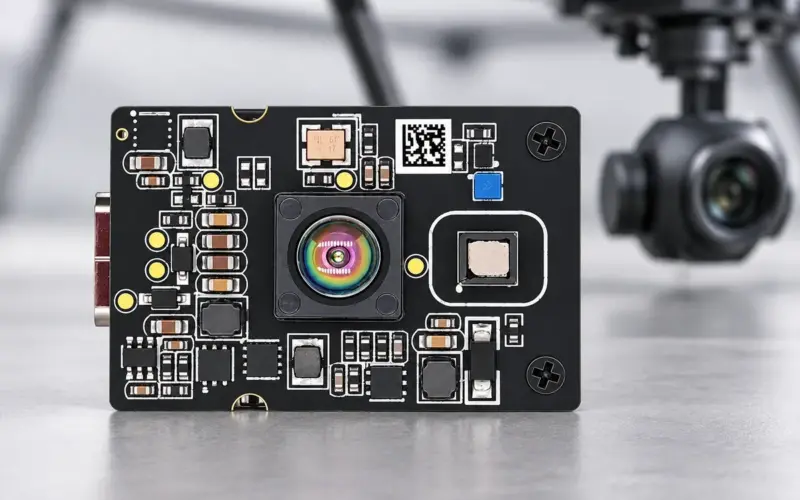
DMOM2508CL provides 320 × 240 depth sampling over 0.2–2 m through a two-lane MIPI interface. Its 21 × 9.5 × 6.33 mm optical head is a starting point for a compact front-view design. Reserve space for the receiving view, emitter clearance, cover, power circuitry and host connection as well as the head itself.
DMOS5030A/5031A offers an onboard-processing route with UART/SPI interfaces configured for the selected firmware. Match the 5030A or 5031A range and field of view to its installation. Decide whether the application needs a depth image, a region result or another agreed output before designing the host interface.
Validate dark floors, gloss and contamination
Build a matrix covering dark carpet, glossy tile, rug edges, sloped transitions and mixed materials. Repeat it with expected window dust, fingerprints, ambient illumination and chassis vibration. Log valid-depth coverage, missed objects, false obstacles, floor-state changes and end-to-end decision timing.
For moving tests, relate decision distance to speed, measured latency and stopping behavior. Use a controlled fixture with physical containment for edge tests. Share the mounting drawing, target list and host platform with us to select a module and evaluation configuration. For the wider perception pipeline, see depth cameras for robot navigation.
Discuss your evaluation with DOMI.
FAQs
Can one forward-facing ToF camera also monitor a floor drop?
Only the floor region inside its usable view contributes measurements. A separate downward installation is often needed to observe the support surface at the required position. Check coverage through chassis motion and near-field blind zones.
What makes a small object difficult to observe?
Its projected size may occupy few samples, and its return can mix with the floor or background. Object material, distance and mounting height should be included in the evaluation alongside nominal resolution.
How should invalid floor measurements be handled?
Give them a defined unknown state in the host algorithm. Test dark and reflective floors separately from real drops, then validate the controller's response for each condition.
Which information helps DOMI select a vacuum sensing module?
Provide front and downward mounting positions, minimum target dimensions, floor materials, decision distance, interface and host processing capacity. These inputs establish the required coverage and data route.