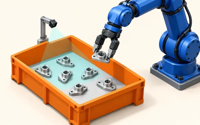

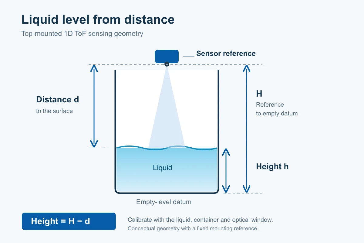
A top-mounted 1D Time-of-Flight sensor measures the distance to a reflecting surface without placing a sensing probe in the liquid. With a defined mounting reference and a calibrated container setup, that distance can become a liquid-height estimate or a refill indication for a reservoir or dispenser.
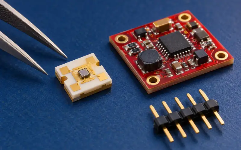
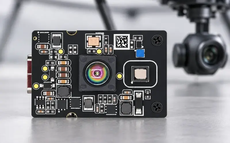
DM0301 brings a compact 940 nm direct ToF sensor and I2C distance output to this design approach. Its 4.40 × 2.40 × 1.00 mm package suits designs with limited sensing space. This guide explains how to evaluate the liquid surface, container and optical assembly together, then connect the readings to your application’s level logic.
Define the liquid level task first
Start with the decision your product needs to make. A low-level refill alert, continuous height display and volume estimate require different calibration and processing.
| Application task | Useful output | Design information to establish |
|---|---|---|
| Refill or low-level indication | A threshold with hysteresis | Switching heights, allowed delay and behavior when a reading is invalid |
| Continuous liquid-height monitoring | Height relative to a fixed reference | Required error in millimetres, usable fill range and update interval |
| Remaining volume estimate | Volume from a height-to-volume relationship | Container geometry or a measured lookup table |
These tasks share a distance measurement, but the host application supplies the conversion, filtering and control decisions.
Evaluate the liquid surface
The returning optical signal depends on the liquid and the complete installation. Use the intended liquid at several known fill heights during evaluation.
| Surface condition | What to examine |
|---|---|
| Clear liquids | Check that readings follow the intended surface as the level changes, rather than an unwanted return from the container or below the surface |
| Dark or opaque liquids | Assess the return at the longest working distance and under the intended lighting |
| Foam or bubbles | Define whether the application needs the foam-top height or the underlying liquid level; compare readings with that reference |
| Ripples, stirring or filling flow | Record changes in readings and choose filtering that meets the required response time |
A change of liquid, concentration or surface condition belongs in the evaluation plan. Keep separate records for the conditions your product will actually encounter.
Match the container to the optical field
Mount the sensor above the intended sensing area and keep the optical path clear of the fill stream, lid edges and internal fittings. Examine the field at the lowest liquid level, where the sensor-to-surface distance is greatest.
DM0301 has a 25° field of view and a 22° field of illumination. These angles describe optical coverage; they are not a pencil beam or a guarantee that a narrow tube will exclude wall returns.
For an initial geometric estimate, a full cone angle θ gives a width at distance d of:
width = 2 × d × tan(θ / 2)
Using the 25° FOV, the calculated width is approximately 222 mm at a distance of 500 mm and 443 mm at 1,000 mm. This is a simplified cone calculation, not a measured sensitivity boundary. Use the actual mounting position, both optical fields and observed readings to assess clearance from the container walls.
For narrow necks, reflective walls or proposed stilling tubes, evaluate the full assembly through the fill range. A tube changes the optical environment as well as the liquid motion; select its geometry from the measurements rather than from the nominal angle alone.
Optical window and enclosure
A protective window can separate the sensor from splashes and residue. Select a window material with suitable transmission at 940 nm and include its spacing, seals and mounting arrangement in calibration.
Check the window in clean, wet and contaminated states representative of use. Include condensation and residue in the maintenance and validation plan. The enclosure should provide the required environmental and chemical protection for the finished device.
DM0301 specifications for design planning
DM0301 provides a single distance channel for the host MCU. Use these sensor specifications to plan the optical and electrical layout, then establish the liquid-level performance in the final assembly.
| Technical specification | DM0301 |
|---|---|
| Measurement principle | 1D direct Time-of-Flight |
| Emitter wavelength | 940 nm |
| Indoor ranging | Up to 4,000 mm |
| Nominal configurable distance range | 20 mm–5 m |
| Ranging rate | Up to 50 Hz |
| Field of view / illumination | 25° FOV / 22° FOI |
| Package dimensions | 4.40 × 2.40 × 1.00 mm |
| Sensor supply | 2.97–3.63 V; 3.3 V typical |
| Host interface | I2C |
| Operating temperature | −20°C to 70°C |
The indoor 4 m specification and nominal 5 m configuration are distinct. Working range and rate depend on target return, ambient light, optical assembly, calibration and measurement settings. Use the nearest full-level distance and farthest low-level distance to choose the operating configuration; the general ranging values do not define a validated liquid-level range.
Convert distance into height or fill percentage
For a vertical top-mounted arrangement, let H be the distance from the calibrated sensing reference to the chosen empty-level datum, and d be the corrected distance to the intended liquid surface:
liquid height = H − d
For a usable range defined by distances d_empty and d_full:
fill percentage = 100 × (d_empty − d) / (d_empty − d_full)
As a geometry example, an empty datum at 500 mm and a full-level datum at 100 mm define a usable height of 400 mm. A corrected reading of 180 mm corresponds to 320 mm above the empty datum and 80% of that usable height.
This percentage represents height. It represents volume only when the container has a constant horizontal cross-sectional area across that range. For tapered, curved or irregular containers, use a geometry model or a measured height-to-volume lookup table. Retain out-of-range readings as a diagnostic condition before limiting any displayed percentage to 0–100%.
Calibrate and evaluate the final assembly
Sensor offset calibration and application-level calibration serve different purposes. DM0301 supports cover-glass calibration, and its offset-calibration guidance recommends a 500 mm reference distance under controlled conditions. That sensor reference does not replace calibration against known fill heights in the intended container.
Use the following sequence to build an application record:
- Assemble the optical path. Fix the sensor, window and enclosure in their intended positions. Record the sensor configuration, firmware and host software versions.
- Establish reference heights. Use an independent level reference and several points across the usable range, including near the refill and full-level thresholds.
- Record repeated readings. Keep the reference height, measured distance, result status or quality indicators supported by the driver, and missing readings. Repeat during filling and draining.
- Characterize the application. Calculate systematic level error, variation at a steady level, valid-reading rate and response time separately. Introduce a correction table only when repeatable measurements support it.
- Exercise operating conditions. Include the actual liquid, illumination, temperature, agitation, foam and window conditions. Repeat on representative assemblies to assess variation.
- Set the host behavior. Choose filtering, threshold hysteresis and the response to stale or invalid readings. Keep the distinction between a valid low-level reading and an unavailable reading.
Set the acceptance criteria around your product’s decision. For a refill alert, threshold repeatability and response time may matter most. For height or volume reporting, evaluate the corrected output across the complete usable range.
Integrate distance acquisition with the host
DM0301 uses a 7-bit I2C address of 0x41. In measurement-application mode, distance is read in millimetres from 0x21–0x22, with the low byte at 0x21. The host sequence includes initialization and firmware loading before ranging.
Our ESP32 and DM0301 integration guide explains wiring, startup and distance acquisition. Apply the liquid-height conversion after the optical assembly has been calibrated, and keep measurement validity handling alongside the level logic.
FAQs
How can a 1D ToF sensor support liquid level monitoring?
A top-mounted sensor supplies a distance reading. Once evaluation establishes that the reading follows the intended surface, the host converts the corrected distance into height using the mounting reference. Refill thresholds or a container-specific volume mapping can then use that height.
What should I evaluate for clear water or a different liquid?
Measure the intended liquid at known fill heights in the actual container. Check the surface return, repeatability and valid-reading rate across the usable range, including the operating lighting and window conditions. Keep the calibration record tied to the liquid and assembly configuration.
How should foam be handled?
Choose the reference your application needs: the top of the foam or the liquid underneath. Compare the sensor readings with that reference under representative foam conditions. If a stilling arrangement is considered, include its walls and geometry in the optical evaluation.
What accuracy should I specify for a liquid-level design?
Specify the required error in millimetres for the final level output, together with the fill range, liquid and operating conditions. Measure error, steady-level variation and missing readings separately after calibration; a millimetre distance output is a reporting unit, not a system accuracy specification.
How do I estimate volume in an irregular container?
Use a container-specific height-to-volume relationship. A measured lookup table can associate known fill volumes with corrected level readings, while a suitable geometry model can provide the same mapping for a defined container shape.
Technical resources and next steps
DM0301 specification reference: Rev. 0.3, December 4, 2023. The product page covers sensor specifications and integration. Our ToF sensor selection page helps place the single-point device within the wider sensing choices.
For background on liquid and container characterization, ST AN5851 and ST TN1450 describe ST sensor implementations. Their product-specific results and software apply to the stated ST devices.
Share the liquid, container dimensions, nearest and farthest surface distances, required level error, window arrangement and host platform with us. Discuss your liquid level sensing design with DOMI so we can help define the sensor selection and evaluation steps.