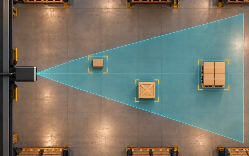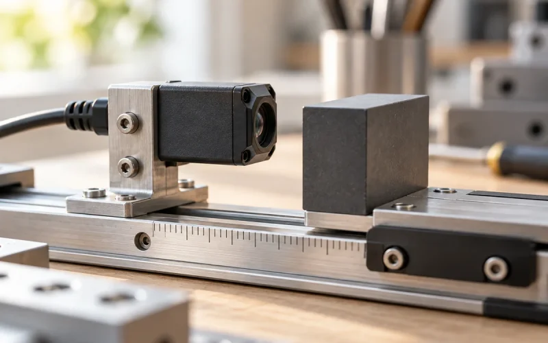

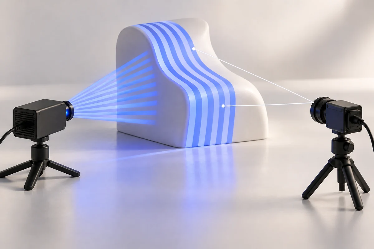
Structured light measures surface geometry by projecting a known pattern and observing it from a different position. The calibrated relationship between the projector, camera and observed pattern allows the system to calculate spatial points through triangulation.
This geometric method differs from ToF ranging, which estimates light's travel delay. Understanding the distinction helps engineers choose a depth-sensing route and identify the calibration, motion and optical conditions each design needs.
What the projector and camera contribute
The projector places a recognizable pattern on the measurement area. Depending on the design, that pattern can include dots, lines or changing fringes. The camera observes how the pattern appears on the target surface.
Calibration relates camera image locations and projector pattern coordinates to rays in space. Once the system identifies corresponding observations, it can calculate where those rays meet or best agree. The spatial arrangement between the projector and camera is part of that calculation.
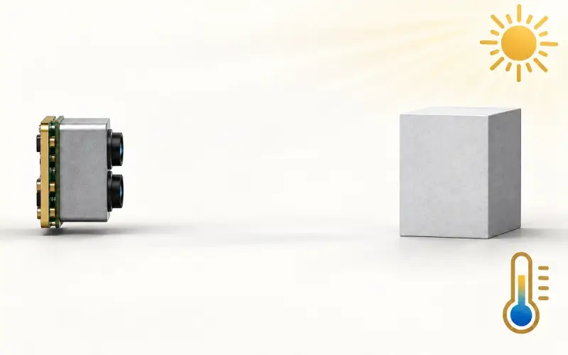
The pattern supplies geometric information. Its observed brightness also depends on the target, exposure, illumination and ambient light, so a readable pattern is a practical requirement for the measurement.
How triangulation produces distance
A camera pixel corresponds to a viewing direction after its intrinsic geometry and distortion are accounted for. A known projected feature supplies another geometric constraint. The separation and relative orientation of the camera and projector allow the depth of that feature to be calculated.
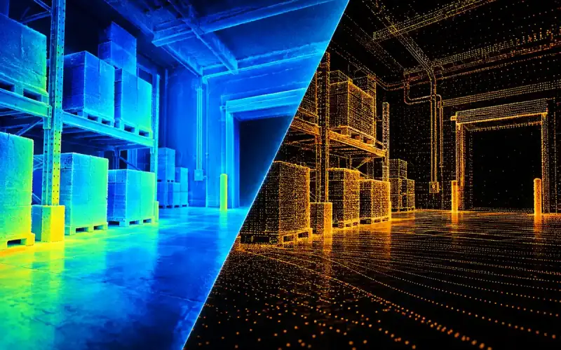
A system then relates the resulting points to the coordinate frame required by the application. The output may be represented as a depth image or point cloud. See depth maps and point clouds for the difference between those data forms.
A simple structured-light triangulation calculation
For a simplified rectified pinhole geometry, a matched projected feature can be expressed with Z = f × B / d. B is the projector-camera baseline, f is the focal length on the common rectified pixel scale and d is the corresponding disparity. With assumed values f = 800 pixels, B = 0.1 m and d = 40 pixels, Z = 2 m. This is a geometric example, not a calibration recipe or accuracy claim for a scanner.
Real systems use calibrated projector and camera models, lens correction and a way to identify the projected feature. With the other terms fixed, smaller disparity corresponds to greater depth; an error in feature correspondence then changes the reconstructed position. The surface must still be visible through the required optical paths.
Single-pattern and sequential measurements
Some designs identify correspondences from one captured pattern. Others project a sequence to encode positions or recover phase information from fringes. The pattern scheme and decoding process determine which observations must belong to the same surface during the measurement.
If the target moves during a sequence, different images can describe different surface positions. Evaluate that interaction using the specific acquisition scheme, exposure and target speed. A single-capture label also leaves timing, occlusions and spatial detail to be checked for the chosen product.
| Design detail | Why it matters |
|---|---|
| Camera and projector calibration | Establishes the geometry used for triangulation |
| Pattern coding and decoding | Determines how corresponding features are identified |
| Projector-camera separation and view | Affects the measurement geometry and shared visible region |
| Target material and ambient light | Affects how clearly the projected pattern can be observed |
| Acquisition sequence and exposure | Determines how motion can affect the observations |
| Mounting stability | Helps preserve the calibrated relationship in use |
Occlusion, reflections and calibration
The useful measurement region must be visible to the required optical paths. A surface hidden from the projector or camera can leave missing geometry. Highly reflective or translucent materials can also change the observed pattern or mix light from several paths.
Calibration should be checked after changes to the optics or mechanical arrangement. Include the final mounting position and protective cover in validation. Evaluate both the quality of reconstructed points and the parts of the target that remain unmeasured.
Where this fits in a depth-camera decision
Compare structured light with ToF using the same working area, target, motion and environmental conditions. A general technology name does not establish the accuracy or working distance of every implementation.
The ToF vs structured light selection guide connects the measurement methods to engineering choices. For the ToF side of a project, our camera module range and technical contact provide a route to model evaluation.
FAQs
How does structured light determine distance?
The system identifies projected features observed by a calibrated camera and uses the projector-camera geometry to calculate their spatial positions through triangulation.
Is structured light a form of ToF measurement?
Structured light triangulation uses geometric correspondence. ToF ranging estimates light's travel delay. Both can produce depth information, using different measurement processes and calibration requirements.
Why does movement matter in a structured-light scan?
Movement can change the surface between observations, particularly when the decoding method uses a sequence of patterns. Evaluate the actual capture scheme and exposure with the target speed planned for the application.