
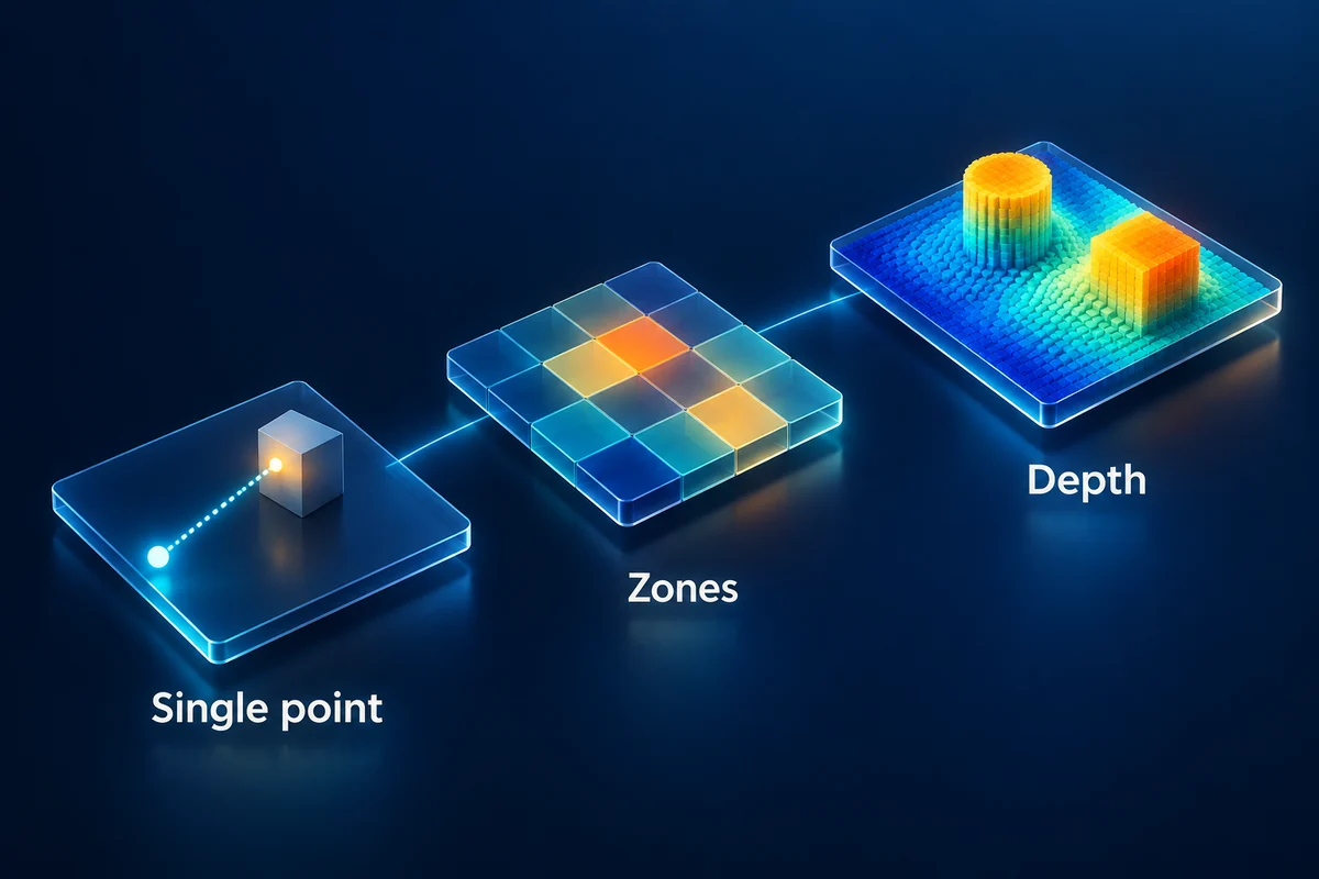
A Time-of-Flight sensor estimates distance from the travel of light between a source, a target and a receiver. Depending on its design, a ToF sensor can provide one distance, ranges across several zones or a depth image. These outputs support different measurement and perception tasks.
For product selection, distinguish the ranging method from the output format. Two devices can both use ToF while providing different spatial information, interfaces and processing requirements.
How does a ToF sensor work?
The system emits light toward a target and detects a portion of its return. Direct ToF estimates the travel delay through timing measurements. Indirect ToF estimates it from signal characteristics, such as the phase relationship of modulated illumination.
Processing turns the measured signal into a reported range, with calibration and methods for handling uncertain returns. For the ideal round trip, distance is half the speed of light multiplied by travel time. The direct and indirect ToF guide explains those routes in more detail.
The components of a ToF system
| Component or function | Contribution to the measurement |
|---|---|
| Emitter and driver | Produce illumination with the required timing or modulation |
| Illumination optics | Direct light toward the intended measurement region |
| Receiver optics and filtering | Collect useful return and control unwanted optical signals |
| Detector and measurement electronics | Capture the information used to estimate travel delay |
| Processing and calibration | Estimate range, apply corrections and report supported outputs |
| Host interface | Deliver data and control information to the application |
Some products integrate many of these functions in one package. Others are components intended to work with external optics, electronics or processing. Identify which level of assembly a specification describes before comparing integration work.
The VCSEL and ToF guide explains how an illumination source fits into that system.
One range, multiple zones or an image
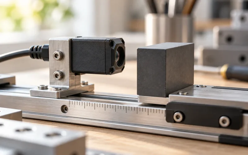
A single-point or single-zone ranging device measures within a defined sensing region. This can suit approach detection, a distance trigger or another task where one region provides enough information.
A multi-zone sensor reports spatially separated measurements. That can help software distinguish where a return appears in the view. Check the zone layout, target behavior and measurement sequence rather than relying on zone count alone.
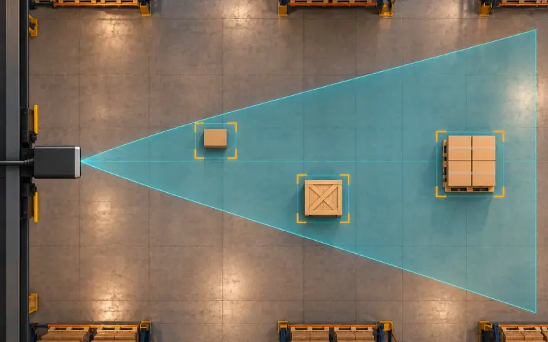
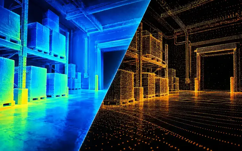
An imaging array supplies depth over many image locations. It can support processing that needs object extent, several surfaces or scene geometry. Resolution, field of view and useful range together determine how much detail is available on the relevant target.
ToF sensor applications by measurement task
| Measurement task | Useful starting point |
|---|---|
| Detect approach within a defined region | Single-point ranging with suitable distance and timing |
| Distinguish activity across several regions | A zone layout matched to the spatial decision |
| Locate object surfaces for robotics or logistics | An array or depth camera with adequate scene coverage |
| Combine appearance with geometry | Color and depth streams with appropriate calibration |
The application software performs recognition, counting, control or other system functions using those measurements. Plan that processing alongside the sensor, including mounting, timing and how uncertain data is handled.
From a ToF proximity measurement to an application decision
A ToF proximity sensor can report distance for software to use in a trigger. A practical data path is measurement, status check, region or distance rule, and then the application action. For example, a dispenser can wake when a valid return enters its approach region; the actuator logic decides how to respond.
Use separate entry and release conditions when the application needs a stable trigger near a boundary. Define how long the condition must persist and how invalid readings are handled. Tune those rules with the actual object and background, then count unwanted triggers and missed approaches. Those outcomes describe the application more directly than a list of industries that could use ToF.
For a spatial task such as locating a parcel edge, start with the zones or image samples needed by the algorithm. The ToF sensor selection guide connects that output requirement to range, timing and host integration. Recognition, people counting and authentication remain software or system functions built on the sensor data.
Conditions to include in an evaluation
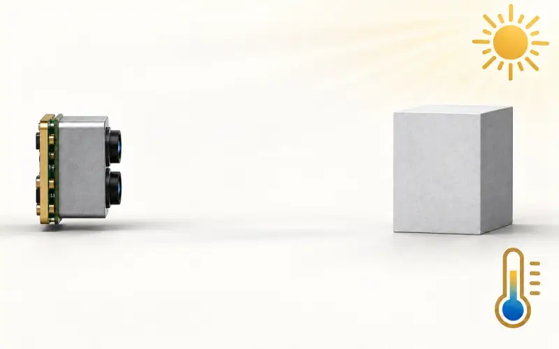
Use representative target materials, distances and angles. Include ambient light, nearby emitters and the final optical cover. Observe missing or rejected measurements as well as error on valid returns.
For embedded hardware, add power in the intended mode, update timing, electrical levels and host software. The ToF sensor selection guide gives a practical order for these decisions.
DOMI sensing options
DOMI offers single-point ToF sensing, array dToF sensing and ToF camera modules. These product formats let the evaluation begin with the amount and type of information required by the host.
Send the measurement task, working distances, target description, required coverage and interface through our contact page. We can help identify a suitable product path and the conditions to include in evaluation.
FAQs
What is the difference between a ToF sensor and a ToF camera?
ToF identifies the ranging method. A ToF camera provides spatial depth information across an imaging field of view. The broader sensor category also includes devices intended to report one distance or several zones.
What are common Time-of-Flight sensor applications?
Applications include proximity measurement, device wake triggers and spatial depth acquisition for robotics, logistics and interaction systems. Choose the output and integration format around the task the software needs to perform.
Does a ToF sensor detect glass or reflective surfaces reliably?
Those materials can produce weak, mixed or redirected returns. Evaluate the selected device with the actual target, angle, background and light conditions, including how the application should handle uncertain measurements.