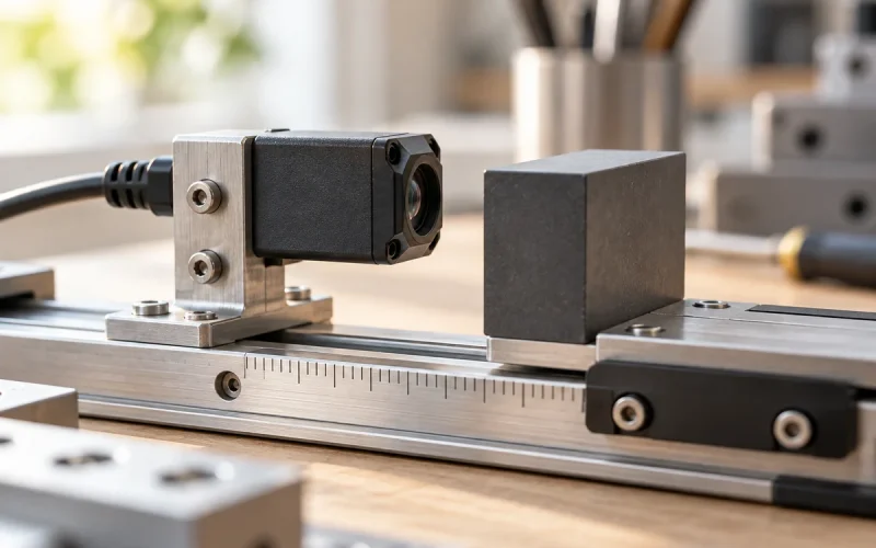

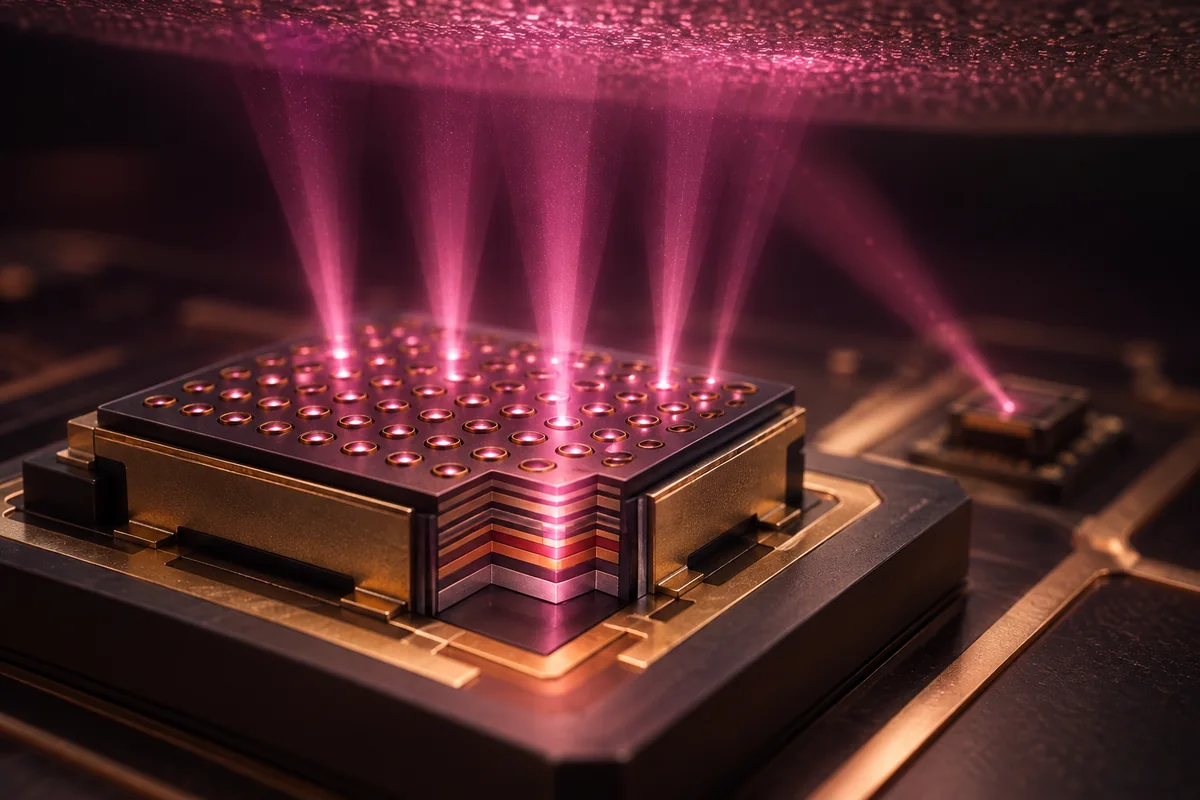
A VCSEL provides the active illumination used by many Time-of-Flight (ToF) sensors. It emits light toward the scene, while the receiver and timing or phase-processing system use the returned signal to estimate distance. This division lets engineers select illumination and reception around the required working area and measurement task.
VCSEL stands for vertical-cavity surface-emitting laser. It describes the laser structure. ToF describes a ranging method. In an integrated module, the light source, driver, receiver and processing operate together to produce the required distance or depth output.
What does a VCSEL do in a ToF system?
The emitter sends pulsed or modulated light into the scene. The illumination optics shape that light for the intended area. A receiver collects part of the return, and the sensor system processes the measurement into distance information.
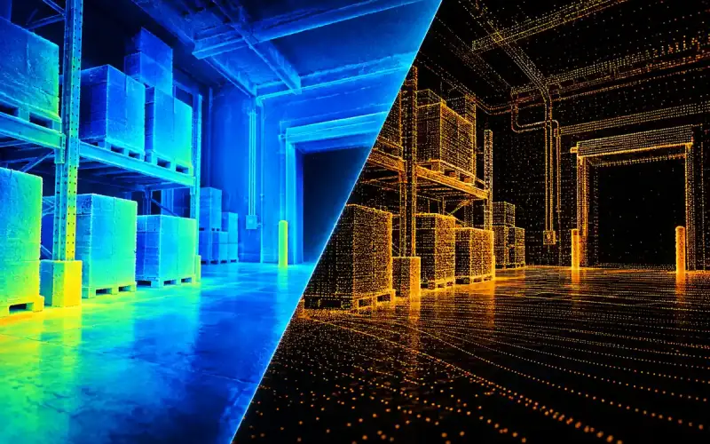
A single-point device may provide one distance. An array can provide several regions or a depth image. The receiver architecture and processing determine those outputs; the VCSEL supplies the illumination used by the measurement.
How illumination and reception work together
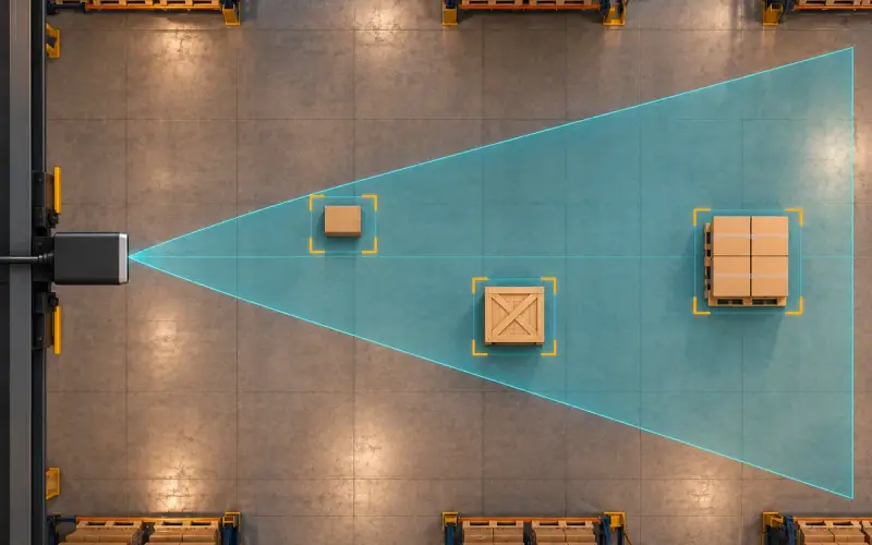
The illumination footprint should suit the region the receiver needs to measure. Light directed outside that region uses power without necessarily contributing to the required measurement. Optical layout, field of illumination and receiver field of view therefore belong in the same design review.
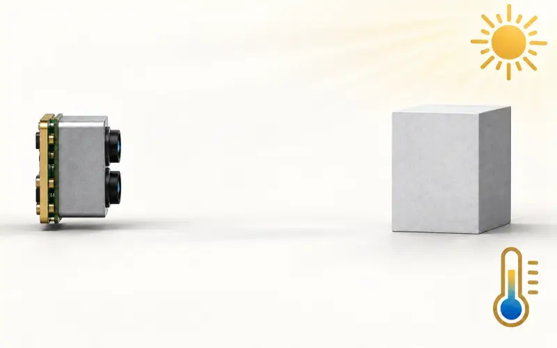
Wavelength also connects the two sides. Match the emitter spectrum with the receiver's sensitivity and optical filter. Include temperature-related changes and the operating conditions of the complete assembly when evaluating the available return signal.
For a phone, wearable or robot, examine the illumination footprint at the working distance, reflections from the optical cover and nearby active sensors. The driver and acquisition timing should support the chosen measurement architecture.
Which emitter characteristics matter?
| Selection detail | Why it belongs in the module evaluation |
|---|---|
| Wavelength and spectral width | Must suit receiver sensitivity and filtering |
| Optical output and operating mode | Identify whether a rating is continuous or pulsed, with its drive conditions |
| Pulse pattern or modulation behavior | Relates the source and driver to the sensor's acquisition scheme |
| Beam shape and illumination coverage | Determines where useful light reaches the scene |
| Electrical drive and thermal conditions | Defines the power and heat-removal requirements of the assembly |
| Package and optical cover | Affects mounting, alignment and internal reflections |
| Applicable laser-safety assessment | Relates the component's rating to the final optical and operating configuration |
Keep peak optical power separate from average optical power. A pulse rating needs its pulse width, duty cycle and temperature conditions. A continuous-wave rating describes a different operating point. These details allow a useful comparison between emitters intended for the same task.
Match illumination coverage and pulse power to the receiver
The field of illumination describes where the source sends light. The receiver field of view describes where returned light can be observed. Compare both at the nearest target plane as well as the farthest one. An image corner can fall outside the illuminated region even though it lies inside the receiver view; light outside the required view also consumes part of the optical power budget.
For an ideal rectangular pulse train, average optical power equals peak optical power multiplied by duty cycle. For example, 10 W peak at 1% duty cycle gives 0.1 W average optical power. This calculation excludes driver losses and is not a drive recommendation, a thermal rating or a laser-safety assessment. Actual emitter limits retain their pulse width, repetition rate, temperature and optical configuration. Match those conditions to the receiver acquisition sequence before comparing two VCSEL sources.
VCSELs, LEDs and other laser sources
VCSELs and edge-emitting devices are both laser implementations. ToF designs can also use LED illumination in suitable architectures. The choice depends on the receiver, wavelength, acquisition scheme, optical coverage and power budget.
For a new design, compare the complete illumination subsystem, including the driver and optics. An emitter's electrical efficiency or component price alone does not establish the depth performance or total integration cost of the module.
DOMI modules and optical-source options
An integrated ToF module provides a defined starting point for the sensing data path. DMAS2M001 combines a SPAD dToF array with 940 nm VCSEL illumination for array depth sensing. DMOM2808D combines QVGA depth sensing with 850 nm illumination and a MIPI CSI-2 host connection.
For optical-source development, our VCSEL and laser-source catalog includes pulsed sensing emitters and continuous-wave modules for other optical tasks. Start with the required wavelength and operating mode, then compare optical output, package, drive and thermal conditions for the intended assembly.
Share your receiver wavelength, illumination area, working distance and drive requirements with us. We can help identify the appropriate product route and the information needed for your evaluation.
FAQs
What does a VCSEL contribute to a ToF sensor?
A VCSEL supplies active illumination. The receiving element measures returned light, and the sensor's acquisition and processing convert that information into distance or depth output. The emitter, receiver and processing should be considered as a complete measurement configuration.
Which light sources can a ToF design use?
Depending on the architecture, ToF illumination can use a VCSEL, an edge-emitting laser or an LED. Compare the wavelength, drive behavior, coverage and receiver requirements of the intended design.
What should I match between emitter and receiver?
Start with wavelength, receiver sensitivity and filter bandwidth. Then evaluate the illumination footprint, optical output, acquisition timing and target return under the required conditions. Include the protective cover and thermal design in the finished assembly.
How should laser-safety information be used in module selection?
Review the applicable information for the specific component and the finished device configuration. The final optics, drive pattern and accessible emission are part of that assessment. Keep component ratings and the complete module's classification clearly identified.
Discuss your sensing or illumination requirements with DOMI.