
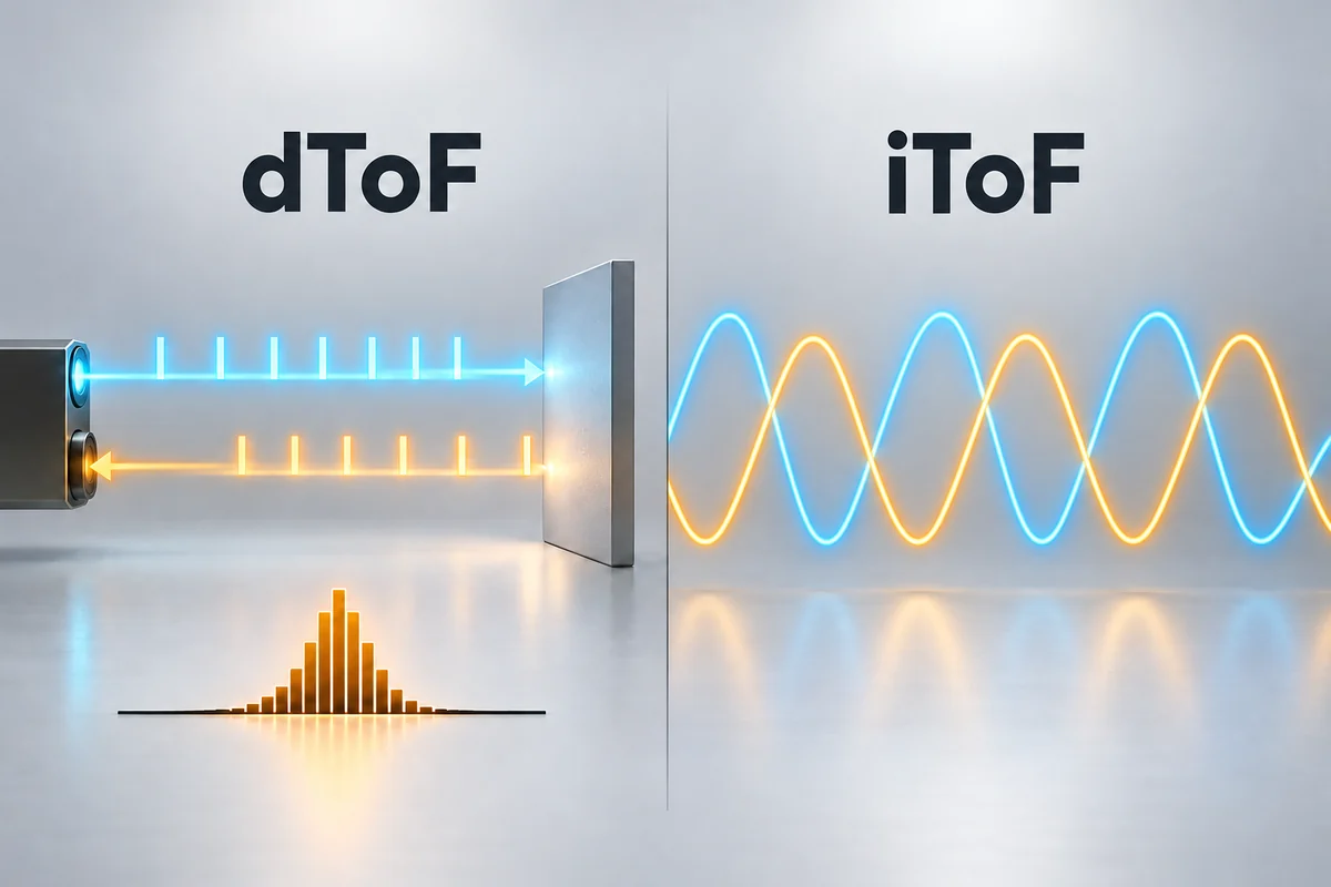
dToF means direct Time-of-Flight. A dToF system estimates range by measuring the time between emitted light and its detected return. An indirect Time-of-Flight system, or iToF, estimates the delay from characteristics such as the phase of modulated light.
The dToF vs iToF distinction describes how a system obtains the delay used for ranging. Selecting a product also requires its spatial output, working conditions, interface and processing arrangement. DOMI provides both single-point and array dToF products for different measurement tasks.
How direct ToF measures distance
Light travels from the emitter to the target and back to the receiver. For an ideal round-trip delay, the distance relationship is d = c × Δt / 2, where c is the speed of light and Δt is the travel time. The division by two accounts for the outbound and return paths.
A practical sensor also deals with fixed timing offsets, background light, noise and the probability of detecting a useful return. Measurements may combine information from multiple emitted pulses. The reported range is the result of the device's timing and estimation process, followed by its applicable calibration.
What SPADs contribute
A single-photon avalanche diode, or SPAD, is a detector that can register very weak optical events. In a dToF receiver, timing circuitry and processing can use those events to estimate a return's arrival time. The detector, timing method, optical filtering and estimation algorithm work as a system.
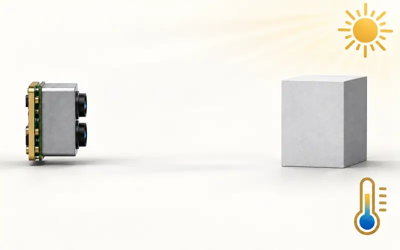
Ambient light can also create detections. The receiver therefore needs a way to distinguish the target return from background events and other unwanted signals. A photon detection is an input to the ranging process, not automatically a complete valid distance measurement.
How iToF estimates delay
An iToF system emits modulated light and samples the returned signal. In a phase-based implementation, the measured phase relationship is used to estimate delay and then distance. Sampling, modulation frequencies and depth processing affect how the system handles noise and distance ambiguity.
A periodic phase measurement repeats. Its useful unambiguous interval and any method for resolving phase wrapping belong to the particular design. Compare those operating details rather than assigning a universal range or accuracy to every iToF camera.
| Question | dToF approach | Phase-based iToF approach |
|---|---|---|
| How is travel delay estimated? | From timing associated with returned light events | From the phase relationship of emitted and received modulation |
| What should the receiver review include? | Detector behavior, event timing, background and return estimation | Sampling sequence, modulation, phase estimation and ambiguity handling |
| Does the architecture determine spatial resolution? | Check the actual receiver array and output | Check the actual receiver array and output |
| What establishes useful performance? | The complete product, mode, optics, processing and test conditions | The complete product, mode, optics, processing and test conditions |
Why phase ambiguity is different from usable sensor range
For an ideal single-frequency phase measurement, one full phase cycle corresponds to an unambiguous distance interval of c / (2f), where f is the modulation frequency. TI’s ToF System Design guide, Chapter 8 gives a 50 MHz example with a 3 m unambiguous range in open air and describes using two modulation frequencies for de-aliasing.
That example concerns phase repetition. Useful target range also depends on return signal, receiver behavior, acquisition settings and processing. A multi-frequency iToF design can resolve ambiguity beyond one phase cycle; a dToF receiver has its own observation window, repetition timing and estimation limits. Ask which operating mode provides the required range and output, then evaluate its error and valid returns. The labels dToF and iToF do not supply those product-level values.
Keep the waveform and measurement method separate
Terms such as pulsed ToF and continuous-wave ToF describe aspects of the illumination and acquisition scheme. They do not provide a complete specification of the estimator or receiver. Some pulse-based systems use gated charge measurements, while photon-timing designs use a different measurement path.
Use the product's actual architecture when comparing these terms. The pulsed and CW ToF guide discusses acquisition timing and motion without treating the labels as a universal performance ranking.
Choose a useful spatial output
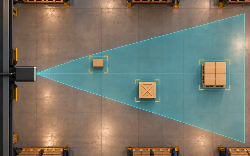
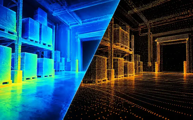
A single-point sensor can support a distance trigger, approach measurement or other task focused on one region. A multi-zone or imaging array adds spatial information. A finer array may help distinguish scene features, while also changing the data and processing requirements.
DM0301 provides single-point dToF ranging with an I2C host connection. DMAS2M001 provides array dToF sensing. These products address different information needs even though both use direct ToF.
For product selection, define the nearest and farthest targets, their size and material, ambient light, required coverage and host platform. Compare error and valid returns under those conditions. We can help identify a relevant DOMI sensing option for the measurement task.
FAQs
What does dToF mean?
dToF stands for direct Time-of-Flight. It refers to estimating the travel delay of emitted light and its return through direct timing, then using that delay to determine range.
Is dToF always better than iToF?
Select between specific products under the same application conditions. Their output, optics, acquisition mode, target return, ambient light, power and processing determine the useful result. The architecture name alone does not establish the better choice.
Is a dToF sensor always a depth camera?
dToF can be used for single-point ranging, several measurement zones or an imaging array. A depth camera is a spatial imaging product; the measurement architecture and the output format are separate parts of its specification.