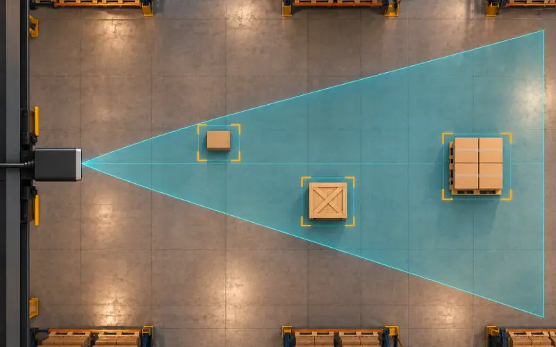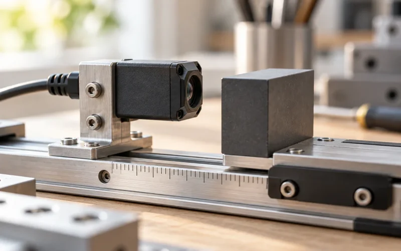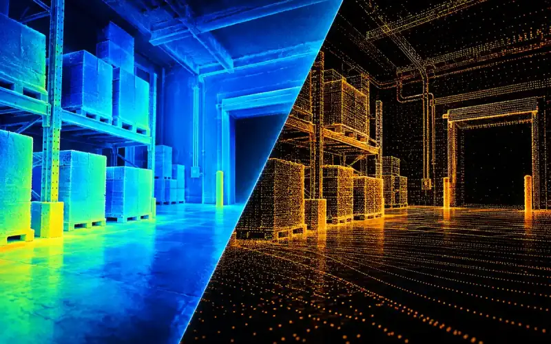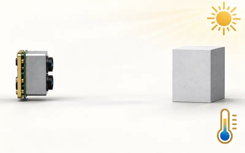

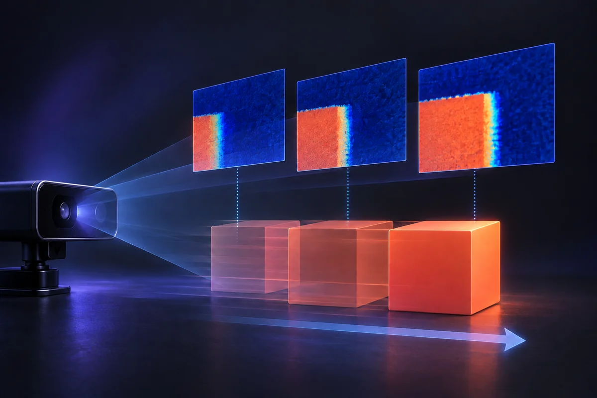
A ToF camera measures over a finite acquisition interval. If a target or the camera moves during that interval, the signal associated with an image location can change. The resulting depth can contain errors around moving edges or other changing parts of the scene.
When comparing pulsed and continuous-wave ToF, examine how the actual camera emits, samples and processes light. Pulse width, integration time and output frame rate describe different parts of that acquisition. A shorter optical pulse by itself does not establish the motion performance of the complete camera.
What changes when an object moves?
A pixel near an object boundary may observe the foreground during one part of an acquisition and the background during another. Mixing those contributions can produce a depth estimate that does not describe either surface correctly. Movement can also alter signal strength, visibility and the position of the object across the image grid.
In acquisition schemes that combine several samples, the surface may change between those samples. Review the timing of all observations used to create the final depth frame, including repeated measurements intended to improve signal quality.
Pulsed and continuous-wave descriptions
A pulse-based system emits light in bursts. Its useful return can be captured through time gating, direct timing or another documented acquisition arrangement. A CW system uses periodic modulation and may estimate range from phase relationships sampled over time.
These descriptions do not fully identify the receiver and estimator. Direct ToF and indirect ToF describe how delay is estimated; pulsed and CW terminology describes aspects of the illumination and acquisition. Read the dToF vs iToF guide for that distinction.
| Timing detail | What to establish for the chosen camera |
|---|---|
| Optical pulse or modulation | The illumination waveform and how it relates to the receiver |
| Integration or acquisition interval | The period over which signals contribute to the depth estimate |
| Sampling sequence | Whether several observations from different times form one depth frame |
| Depth frame interval | How frequently a completed depth frame becomes available |
| Processing and transport | Delay between measurement and the application's use of the data |
| Exposure or mode changes | Whether the camera adapts its acquisition to the scene |
Balance signal quality and motion
A longer acquisition can collect more useful return, while allowing more movement during the measurement. Shorter acquisition can reduce that movement but also changes the available signal. The useful operating point depends on illumination, receiver sensitivity, target reflectivity, ambient light and processing.
Check whether changing exposure also changes the output mode, valid-return rate or update timing. Compare motion performance together with the depth data available to the application, not only the apparent sharpness of a display image.
Estimate how far a target moves during acquisition
As a planning calculation, target displacement during acquisition is speed × acquisition interval. A target moving laterally at 1 m/s travels 5 mm during a 5 ms interval. If its footprint on the target plane is 4 mm per depth sample, that motion is about 1.25 sample spacings. These assumed values illustrate timing; they are not measurements from a camera.
Compare that displacement with the smallest feature and foreground-background boundary your software uses. Output frame rate alone does not provide the acquisition interval. When a frame combines observations at different times, include the time spanned by the contributing samples. Temporal smoothing can also mix information across frames, so retain the filter configuration in the static-versus-moving comparison. Use the field-of-view calculation to estimate the target-plane sampling, then evaluate the actual camera mode.
Test static and moving scenes separately
Start with a fixed camera and a fixed target to establish baseline depth behavior. Include the materials, distance and edges expected in the application. Then introduce the intended target or camera motion while retaining a record of the acquisition configuration.
Record which parts of the scene develop missing depth, mixed-edge values or inconsistent geometry. Include the moving object's speed and direction relative to the camera, its size in the image and the background distance. Check frame timestamps and the time at which the application receives or uses the measurement.
For multi-camera installations, test the intended devices together. Synchronization or interference handling depends on the models and configuration; changing the illumination schedule can also change the timing available to the application.
The ToF accuracy testing guide provides a framework for recording error, conditions and valid data. The camera selection guide connects timing to coverage and host integration.
Compare a complete camera mode
Use the same target, distance, scene coverage and ambient conditions for the candidates. Identify which settings the application can control and which are managed by the device. Compare power and thermal behavior in those modes, including any host processing required to obtain depth.
For a moving-platform project, send your target or camera speed, working range, object size and host platform to DOMI. We can help define an evaluation around the data and timing the application needs.
FAQs
Does a pulsed ToF camera eliminate motion blur?
Motion behavior depends on the complete acquisition and processing sequence. Review pulse timing, integration, repeated samples and frame processing for the chosen product, then evaluate the actual moving scene.
Is frame rate the same as acquisition time?
Frame rate describes how often frames are produced. Acquisition time describes the period contributing measurements to a frame. Processing and data transfer add further timing that may matter to the application.
Are CW ToF and iToF interchangeable terms?
They describe different aspects of a system. CW refers to periodic illumination or modulation, while iToF refers to indirect delay estimation. Use the product's documented architecture when identifying how those descriptions apply.