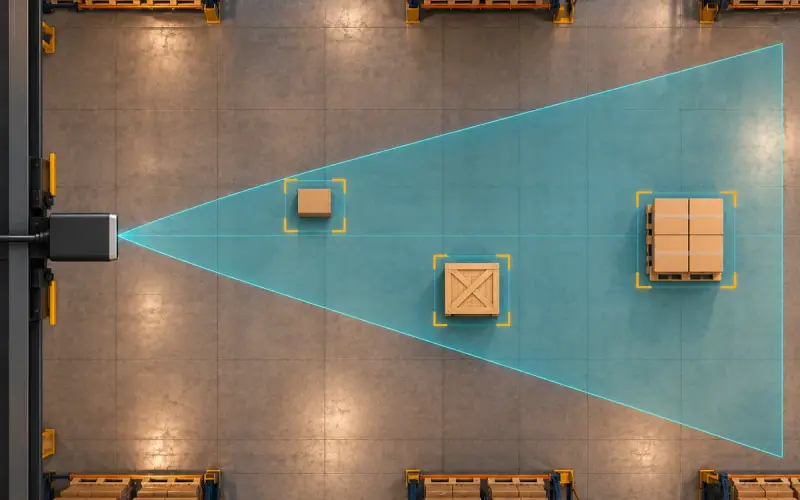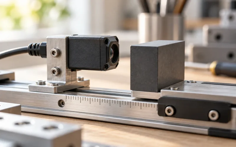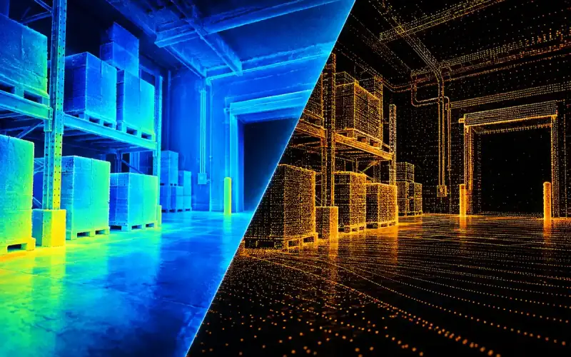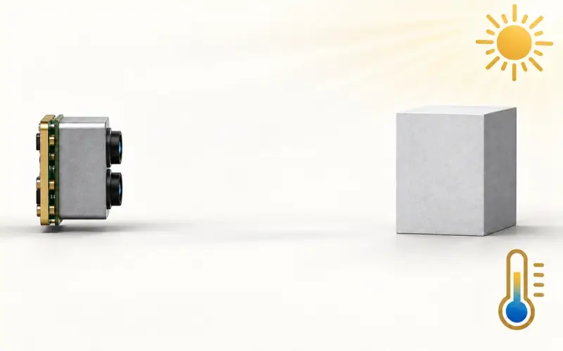

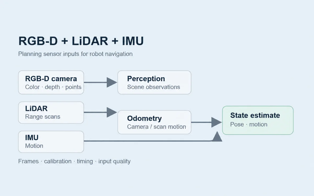
Plan RGB-D, LiDAR and IMU fusion around the observations your robot needs. A camera supplies appearance and depth, LiDAR measures geometry within its scan coverage, and an IMU supplies motion-related measurements. Assign each input to a host processing stage and define the output that stage must deliver.
Obstacle perception may use depth points after conversion and filtering. Localization may use motion estimates or geometric constraints derived from sensor data. Coordinate frames, capture times and input quality determine how those observations can be used together.
Define the navigation task and required observations
An AMR approaching a loaded pallet has several tasks to complete. It needs observations of nearby objects for path planning, a pose estimate for navigation, and visible pallet features for the final approach. Define the output for each task before selecting the sensor combination.
| Input | Observations available to the host | Processing to plan | Output to evaluate |
|---|---|---|---|
| RGB-D camera | Color images and depth samples; point clouds where provided by the selected camera or software | Image/depth correspondence, depth conversion, filtering, object or feature processing | Scene geometry, object observations or visual/depth odometry, according to the chosen software |
| LiDAR | Range samples organized by scan direction, with coverage determined by the scanner | Scan conversion, filtering and, where required, matching against another scan or map | Obstacle geometry or motion/pose constraints |
| IMU | Angular velocity and linear acceleration; an orientation estimate where provided by the device or driver | Units and axes, mounting transform, timing, bias and gravity treatment required by the estimator | Motion observations accepted by the selected estimation software |
Name the software component that produces each output and the component that consumes it. Record the observation region and the operating conditions: robot motion, load position, lighting, target surfaces and changes along the route.
Use these requirements to decide which sensors serve each task. A camera may supply nearby three-dimensional object detail while a scanner supplies geometry over a different region. Plot both views on the installed robot; their usefulness depends on which surfaces remain visible during motion and with the intended load.
Separate perception data from state-estimation inputs
A depth image describes distances to observed surfaces. A robot pose describes the robot’s position and orientation relative to a reference frame. Connecting the two requires processing that relates observations to a scene, map or earlier observation.
In this example, camera data serves local perception and camera odometry. Scan matching and prepared IMU observations also feed the state-estimation path.
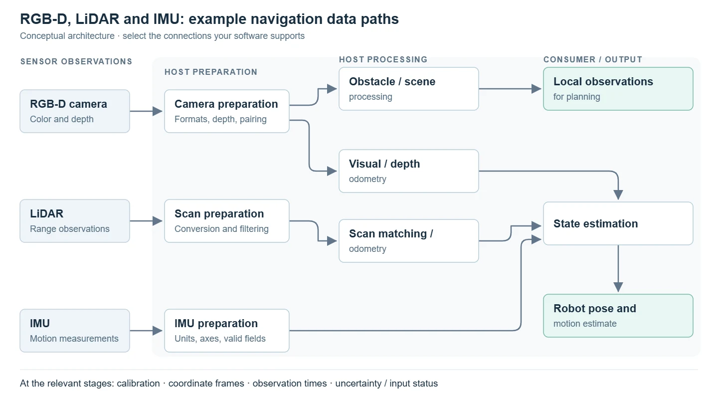
Example host architecture. Calibration, coordinate frames, observation times and input uncertainty accompany the relevant stages. The selected software determines which connections are used.
The perception branch produces scene observations for local planning. In the estimation branch, camera and scan processing provide odometry alongside prepared IMU observations. For each estimator input, record the measured quantity, coordinate frame, observation time and uncertainty information. Choose the fields and connections supported by the selected estimator.
An estimator designed for pose and motion messages needs upstream processing to turn images or scans into those inputs. Use the interfaces of your selected software to determine where matching and estimation take place.
Trace camera data through the host pipeline
For the camera branch, follow one capture from driver output to its consumer. Identify whether the software expects a depth image, a point cloud, RGB paired with depth, or an odometry result. Keep the calibration, distance convention, coordinate frame and observation time associated with that capture through conversion.
For example, the RTAB-Map ROS package documentation separates odometry, synchronization, SLAM and processing utilities into distinct packages. Use that separation to assign processing responsibilities when evaluating a pipeline. Check the selected release and camera integration before choosing the exact connections.
Record the input, output and failure indication at each connection. If a pose update stops, those records help distinguish a missing camera capture from a failure in conversion, matching or estimation.
Align coordinate frames, calibration and capture time
Each sensor observes the world from its own position and orientation. Define the robot reference frame, each sensor frame and the transform direction between them. Keep units and axis conventions with the data, including any camera optical-frame convention used by the driver.
For RGB-D processing, check the camera intrinsics, depth scale and depth convention. When combining color and depth from separate optical paths, use the relevant RGB-to-depth calibration and validate correspondence across the shared working region. Then establish the installed transform between the camera and robot, and the corresponding transforms for LiDAR and IMU.
Use a known, stationary scene to inspect whether transformed camera and LiDAR geometry agree where their views overlap. Check more than one target position and distance. Inspect IMU axes against known robot orientations and motions, using the device and estimator documentation to establish the expected behavior.
Keep spatial and temporal alignment separate
Spatial registration relates observations to the same geometry. Temporal alignment relates them to the time at which that geometry was observed. A stationary target can look aligned even when two captures are separated enough in time to disagree during a turn.
For each stream, establish what its timestamp represents, which clock produced it, and how that clock relates to the others. Distinguish capture time from arrival and processing time. With moving scenes, record the capture-time difference between paired observations as well as the age of the result when its consumer uses it.
Software that pairs messages by timestamps needs an application-appropriate matching rule. Pairing messages in a host queue does not make their physical captures simultaneous. Use representative robot motion to assess the effect of the remaining time difference and to set the acceptable input age for the consuming software.
The RGB-D calibration and validation guide explains reference captures, color-depth registration and validation of the finished camera installation.
Plan host processing and degraded inputs
Build the host budget around the streams you will actually enable. Record their formats, dimensions, rates, transfer path and processing stages. Include conversion, copying, synchronization queues and logging when measuring the workload. Measure the age of the output under representative host load, alongside throughput.
Give each consumer a defined response to unusable inputs. For depth, preserve the distinction between a valid distance and an invalid sample. For images and scans, track interrupted, stale or unmatched observations. For IMU or derived odometry, preserve the meaning of unavailable fields and uncertainty information through conversion.
The ROS IMU message definition, for example, distinguishes unknown covariance from an unavailable estimate. Document how uncertainty is obtained, using device information or project measurements where applicable. Preserve the message conventions for unknown or unavailable estimates when adapting data for the selected estimator.
| Condition to investigate | Evidence to retain | Consumer behavior to define and test |
|---|---|---|
| Sparse or missing depth in the task region | Raw depth, valid-data mask where available, scene conditions and processing settings | How perception represents unobserved space and reports input availability |
| Delayed or interrupted camera/scan stream | Capture and receipt times, queue behavior and output age | Which observations become stale and how the consumer responds |
| Matching or odometry produces no update | Source captures, tracking status and the last usable output | How downstream estimation detects and handles the interruption |
| IMU fields or uncertainty information are unavailable | Original messages, driver settings and documented field conventions | Which measurements the estimator accepts or excludes |
Test these conditions and expose input availability to downstream software. During an interruption, check which inputs continue contributing to the output and how the system indicates whether that output remains usable.
Validate the installed sensor pipeline
Set acceptance criteria for the task before running the evaluation. Keep input quality, localization error and obstacle-perception results as separate measurements so a good result in one area cannot conceal a failure in another.
| Validation question | Measurement to plan | Conditions to record |
|---|---|---|
| Do observations agree geometrically? | Transformed target positions or surface agreement against known references | Calibration version, mount transforms, target positions and measurement uncertainty |
| Are observations available when needed? | Valid depth in the task region, missing observations, stream gaps and recovery intervals | Target material, light, load, sensor view and stream settings |
| How well does the robot estimate motion or pose? | Position and orientation error against an independent reference appropriate to the task | Reference frame, reference timing, route, speed and the inputs enabled |
| How old is the information used downstream? | Capture-to-consumer time, its distribution and trials with no usable result | Normal and peak host load, queue settings and processing configuration |
| Does perception support the intended task? | Obstacle misses and false reports, or availability of the feature needed for approach | Defined targets, clear-path trials, route segment and task-specific pass criteria |
Begin with stationary reference checks, then repeat with representative translation and turns. Include the installed enclosure, optical window, payload and host configuration. Introduce controlled stream interruptions in an appropriate test setup to check degraded behavior and recovery.
If the project needs evidence that an additional sensor improves a result, compare matched runs with the sensor combinations being considered. Keep the route, references and evaluation method consistent, and retain failed trials. Record the hardware, firmware, software, calibration and estimator settings with the captures so the comparison can be repeated.
For detailed mounting, coverage and motion-response checks on a mobile robot, use the AMR camera installation and validation guide.
Choose camera inputs and supporting resources
DOMI’s compact USB RGB-D cameras bring color detail and ToF depth into host-based robot perception. Combining appearance and geometry gives engineers inputs for identifying visible features and examining their spatial relationships within the camera’s working view.
For a pipeline that needs depth maps or point clouds, review DM-RGBD5003A’s data and software options. It provides RGB images, millimeter distance maps and X/Y/Z point clouds. Development options include a C/C++ SDK, a Python wrapper and ROS 1 / ROS 2 packages. Match the required camera output to the host software, then confirm the package version, calibration and timestamp behavior for the selected configuration.
DM-RGBD5002A provides another USB color-and-depth route. Compare its documented outputs and software platform options with the same input requirements. Camera selection establishes the data source; the host architecture determines how that data joins LiDAR and IMU processing.
Compare RGB-D camera inputs to shortlist the camera format and data path for your design.
To discuss camera input requirements, share your host platform, required outputs, working region, mounting arrangement and timing needs. Include the software components that will consume the data so the discussion can focus on the camera’s role in your navigation architecture.