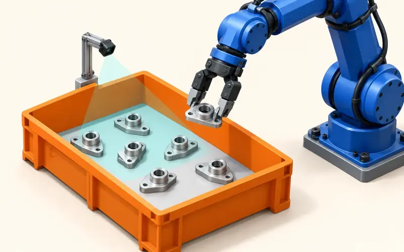

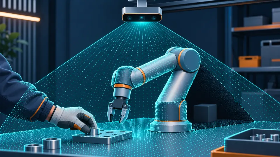
A robot arm can block the camera’s view as it moves across an assembly bench. An operator placing a component changes the visible scene again. A Time-of-Flight camera gives host software depth observations for representing that workspace. Useful perception starts with the surfaces the camera can observe and the position and time attached to each observation.
When evaluating a ToF camera for collaborative robots, define what the application needs to observe through the working cycle. Use that task to plan coverage, calibration and host processing before selecting a camera configuration.
Define the shared-workspace sensing task
Specify the region and the changes the application needs to observe. For example, an assembly task might need depth over the bench and an adjacent component-placement area. Record the nearest and farthest required points, the smallest relevant feature and the robot poses that affect visibility.
Choose the data around the host algorithm. A depth map associates distance samples with image pixels; a point cloud supplies three-dimensional coordinates for geometric processing. RGB adds appearance information when visual features help the task. Retain the units, coordinate conventions, calibration and available timing information with those observations.
Define the host output as carefully as the camera input. A workspace model needs rules for interpreting changes and unobserved regions. Human identification or body-part tracking, when required, needs suitable perception software and its own evaluation beyond acquiring depth frames.
Plan camera coverage and occlusion
Check the view throughout the intended robot motions, including the gripper and carried component. A region visible with the arm parked may be hidden during a transfer. Include likely operator positions in the placement study, since an operator can also obscure the work surface.
A single camera observes visible surfaces along its lines of sight. Keep hidden regions marked as unobserved; missing depth must not become evidence that an area is empty. If another view is considered, check which previously hidden surfaces become visible, how the views will share coordinates and whether simultaneous camera operation changes depth quality in the selected modes.
Match working distance and field of view to the required region. For processing that combines color and depth, check the coverage shared by both streams. Evaluate representative clothing, dark components, reflective tools and packaging under the intended lighting. Record missing depth and unstable boundaries before and after filtering to see whether processing removes information the task needs.
Relate depth observations to robot coordinates and time
Use the camera’s calibration and documented depth convention when converting distance samples into geometry. Establish the camera-to-robot transform so observations can be expressed in the frame used by the application. Check transform direction, units and axes against reference locations across the working region.
RGB-depth registration relates the camera’s color and depth geometry. Camera-to-robot calibration relates that geometry to the installation. Moving the camera calls for checking its relation to the robot even if the internal RGB-depth geometry is unchanged. The RGB-D calibration and validation guide explains reference captures, alignment and final-assembly checks.
Identify what each available timestamp represents: image capture, device output or host receipt. Establish how the camera observations and robot-state times can be compared. If timing information covers only part of the path, record that limit in the evaluation. Frame rate alone does not give the age of an observation when the application uses it.
Measure transfer, queueing and host processing under representative load. Compare stationary and moving captures so the evaluation can distinguish a spatial mismatch from observations paired at different times. Set the acceptable observation age from the application’s needs.
Keep perception and protective functions distinct
Assign responsibilities before deciding whether the camera output meets the task.
| System element | Responsibility to define |
|---|---|
| Camera and acquisition software | Supply selected depth, RGB or point-cloud data with the available calibration and timing information |
| Host perception software | Interpret observations, retain unknown regions and produce the required workspace information |
| Robot application and controller | Use that information within the defined operating workflow |
| Protective sensing and control | Address the installation’s protection requirements through an assessed and validated system |
Depth images alone do not provide a complete personnel-protection function. Protective sensing and control require their own suitability assessment and validation for the installation. Evaluate a general perception input by the observations it provides and the host task it supports.
For a research example, Hietanen and colleagues’ 2019 paper, AR-based interaction for safe human-robot collaborative manufacturing, combines a depth-based workspace model with robot-state information and a separate user interface. The researchers used their own camera, robot and interface configuration.
Evaluate the installed perception pipeline
Define acceptance criteria for the observation region, spatial agreement, timing and host output before collecting evaluation captures. Use reference geometry or recorded scene events to check the relevant output, with validation captures separate from those used to establish calibration.
| Check | Conditions to include | Results to record |
|---|---|---|
| Coverage and occlusion | Required regions through representative arm, tool, component and operator positions | Observable areas, hidden regions and when visibility changes |
| Depth quality | Required distances and image regions, target surfaces and lighting | Reference error where measured, variation, missing depth and boundary behavior |
| Spatial correspondence | Reference locations expressed in camera and robot frames | Transform direction, units and disagreement at those locations |
| Timing | Moving scenes and representative host load | Timestamp meaning, clock relationship, processing delay and observation age at use where measurable |
| Host interpretation | Task-relevant scene changes and missing or delayed input | Expected output, missed or false interpretations and the application’s handling of unavailable observations |
Save camera settings, mounting details, calibration files and the host-software configuration with the results. Revisit the affected checks after changing the installation, capture mode or processing. Keep depth error, interpretation behavior and timing as separate results so a later adjustment addresses the observed problem.
Review camera inputs and technical resources
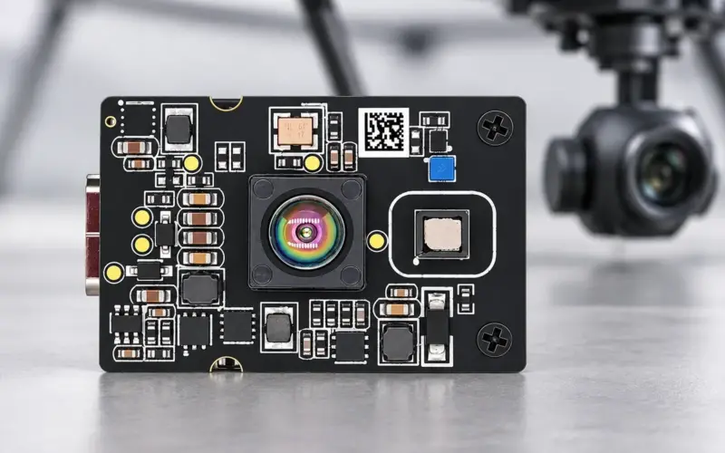
DOMI’s DM-RGBD5003A depth and point-cloud outputs combine VGA ToF depth, RGB images and X/Y/Z geometry for host-based perception development. Color adds visual detail to the workspace observations, while depth maps and point clouds give software inputs for geometric processing.
Its compact USB 2.0 camera format and development options, including a C/C++ SDK, Python wrapper and ROS 1 / ROS 2 packages, give engineers routes into an existing host workflow. Match the package and configuration to your processor, operating system and software version. Evaluate the selected streams with the installation’s coverage, calibration and timing requirements.
Review RGB-D camera inputs to compare camera configurations and development routes.
To discuss workspace sensing inputs, share a workspace sketch, required observation distances, representative surfaces, mounting options, host platform and required output. Include robot motions and the observation timing your application needs.