
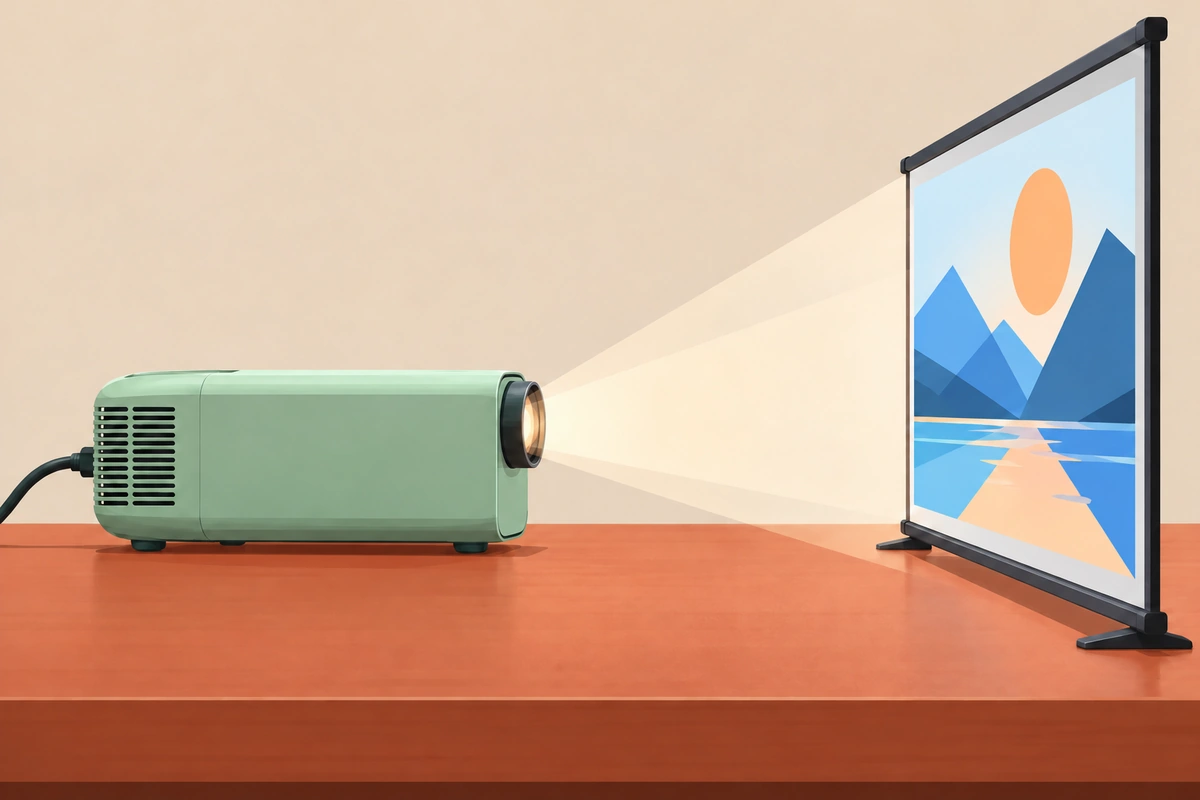
A projector can use a ToF distance measurement as an input to focus control. An area-depth view can also contribute surface geometry for a separate correction pipeline. Define the focus and projection tasks first so the selected sensor provides the information each one needs.
Define focus distance and projection geometry
Specify the screen distance, projector offset, expected tilt, movement and acceptable focus-settling time. Identify the surface region that should determine focus when the sensor can see a wall, screen frame or nearby object at different distances.
Focus concerns lens setting for the target image plane. Keystone correction concerns the relationship between the projected image and the receiving surface. Multi-projector alignment and blending add image registration and photometric requirements. Give each function its own input and validation criteria.
Convert range input to lens control
Calibrate the relationship between measured range and the lens actuator for the selected optical system. A lookup table or fitted mapping can provide an initial lens position, with an image-based focus check or other feedback where the design uses it. Include mechanical tolerances and temperature-dependent behavior in testing.
Define how the controller qualifies a distance, rejects irrelevant targets and responds after the projector moves. Record capture, filtering, lens movement and settling delays. Test repeated near-to-far and far-to-near changes to expose backlash or unstable adjustment.
Separate single-point focus from plane estimation
A single-zone range can support focus when it observes the intended screen region. Estimating screen orientation needs multiple spatial constraints, such as usable points spread over a depth image, together with calibration relating the sensor to the projector.
Fit a plane using appropriate valid points, then check its residuals and coverage. The projector's optics and rendering pipeline use that plane under their own geometric model. A distance value alone does not define the complete image warp or a multi-projector blending solution.
Compare single-zone and area-depth routes
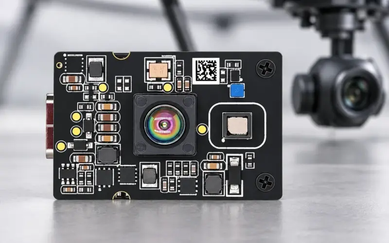
DM0301 offers single-zone processed distance through I²C for a host-controlled focus input. DMOS5030A/5031A provides up to 100 × 100 depth sampling and onboard processing. DMOS5030A combines a 30° × 30° field of view with 0.2–4.8 m range; DMOS5031A combines 60° × 60° with 0.2–2.5 m. Their selected firmware and interface configuration should match the required output.
For an area view, calculate the footprint on the screen at the nearest and farthest distances. Select the region used by focus or plane fitting so a foreground person or screen border does not silently replace the intended target.
Validate screen materials, angles and cover window
Test matte screens, painted walls and other intended materials at representative angles and ambient illumination. Include dark scenes, screen edges, foreground occlusion and expected window contamination. Evaluate the installed cover's transmission and optical coupling rather than the exposed module alone.
Report usable-distance rate, range stability, final image focus and time to settle. For geometric correction, compare the resulting image geometry against a reference grid separately from focus. Send us the throw-distance envelope, screen region, optical layout and host interface to plan a ToF evaluation.
Discuss your evaluation with DOMI.
FAQs
How does a ToF distance help projector autofocus?
The focus controller maps the measured screen range to a lens setting using calibration for its optics and actuator. Feedback and settling behavior are evaluated in the complete projector.
What additional information does keystone correction need?
It needs sufficient surface geometry and a calibrated relationship between the sensor and projector, followed by an appropriate image-warping method. One range measurement does not define the screen plane.
When is an area-depth sensor useful?
It is useful when the application needs spatial regions or multiple surface points, such as selecting a screen region or estimating a plane. Check field of view and valid coverage at the working distance.
Which tests should accompany sensor selection?
Test intended surfaces, angles, lighting and covers, then measure the final focus and geometry results. Keep distance stability, lens settling and image-correction error as separate metrics.