To connect an RGB-D depth camera to RTAB-Map in ROS 2, trace color images, depth images and their calibration from the driver to the consuming nodes. Check image geometry and depth units first, then coordinate frames, timestamps, synchronization and delivery.
A visible image stream confirms only part of that path. The odometry or mapping node needs a consistent set of inputs at the expected observation time. Checking each stage helps locate the first mismatch before changing downstream settings.
Use the checks below with the documentation for your installed camera driver and RTAB-Map version. If you are still choosing hardware, start with our ROS 2 depth-camera selection guide.
Identify the camera and RTAB-Map input path
Record the camera model, firmware, driver, ROS 2 distribution, RTAB-Map package version, operating system and processor architecture. Include the ROS middleware implementation when investigating delivery problems. These details let you compare the running system with the appropriate official example.
In the RTAB-Map ROS 2 stack, synchronization, odometry and SLAM have separate roles. A configuration can pass separate image and calibration topics to a consumer, or combine camera inputs into an rtabmap_msgs/msg/RGBDImage message first. Identify which route your launch configuration actually uses.
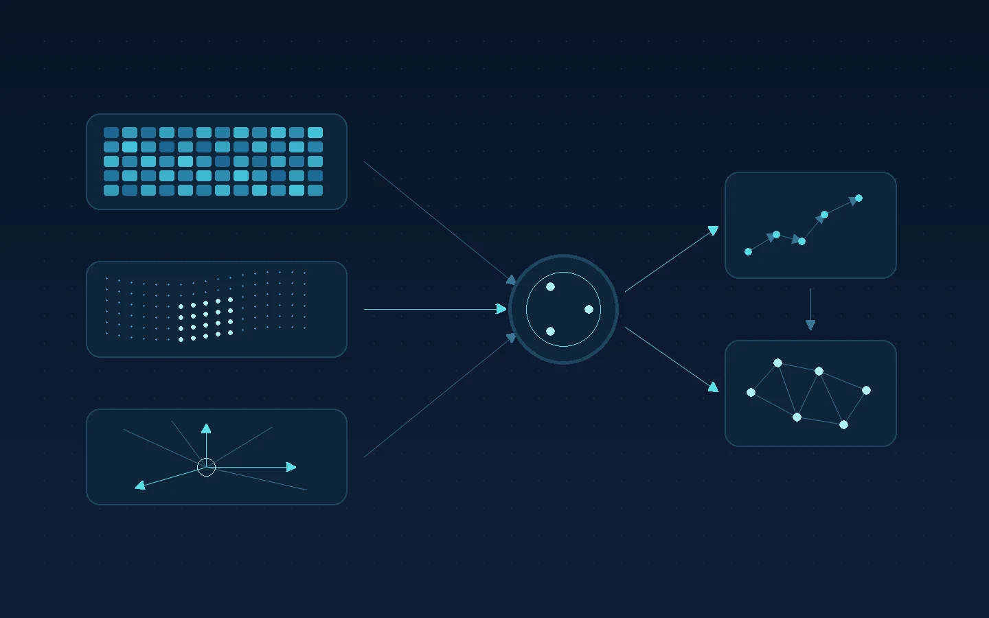
This conceptual path shows one RGB-D arrangement with visual odometry. Its labels describe generic data roles:
Camera driver → color + registered depth + calibration
                         ↓
                 synchronized RGB-D observation
                    ↙                 ↘
          RGB-D odometry ── pose ──→ SLAM
An external odometry source can supply the pose instead. Camera-to-robot transforms must also be available to the nodes that need them. Check the odometry package documentation for the selected arrangement.
For the documented rgbd_sync route, the depth image is registered to the color camera and the calibration describes that color-camera geometry. Trace those inputs together when checking topic remappings. The official node reference explains the accepted messages and output.
Check image data and camera calibration
Inspect the messages delivered to the consumer, including any conversion or registration between the driver and RTAB-Map. Build a short input record:
| Input | What to record | Check against |
|---|---|---|
| Color image | Topic, encoding, dimensions and frame ID | The image stream selected by the launch configuration |
| Depth image | Encoding, units, invalid values and dimensions | The driver’s output description and the consumer’s accepted format |
| CameraInfo | Calibration, image geometry and frame ID | The image and registration path that the consumer uses |
| Timing | Header stamps and observed delivery | The synchronization policy and clock used by the system |
The ROS Image definition describes acquisition timestamps, optical frame IDs and pixel encoding. Each image and its associated CameraInfo must use consistent frame IDs. The CameraInfo definition distinguishes raw-image intrinsics from the projection model for processed images. Account for resizing, cropping or rectification when checking their correspondence.
Keep depth scale and image registration explicit
Depth units belong with the data throughout conversion. REP 118 defines floating-point depth in meters and an alternative unsigned 16-bit representation in millimeters, where zero indicates invalid depth. The linked rgbd_sync reference accepts 16UC1 depth in millimeters or 32FC1 depth in meters. Compare the actual driver messages with the interface for your installed version before applying a scale conversion.
REP 118 expresses depth along the camera Z axis. For a basic scale check, compare a stationary target’s depth with its known distance along that axis. Preserve invalid-depth handling so missing measurements remain distinguishable from surfaces.
Registration needs a separate check. Overlay the selected depth and color images and examine edges at several distances within their shared view. Matching image dimensions alone does not confirm that the pixels refer to the same rays. If the stream is registered to the color camera, use the calibration appropriate to that registered output. Our RGB-D calibration and validation guide explains how to separate scale, alignment and timing checks.
Check transforms and observation time
Follow the actual frame IDs from the image and calibration messages to the robot frame used by the consuming node. Confirm the mounting translation and rotation, and check that the required transform is available at the observation time.
Camera optical axes differ from the usual robot-body axes. REP 103 defines the optical convention as x right, y down and z forward; the body convention is x forward, y left and z up. Check the transform between those conventions before investigating an apparently rotated scene.
Then compare image timestamps with transform and odometry timing. Identify whether the system is using live time or replay/simulation time, and how the driver relates device time to ROS time. A correctly measured mounting transform can still be unavailable for a particular image timestamp.
Observe the scene at rest and during controlled motion. If color and depth agree at rest but separate during movement, examine capture timing and buffering alongside spatial calibration. Keep the camera’s acquisition time distinct from the time the host finishes receiving or processing the image.
Diagnose synchronization, QoS and queues
Start by checking whether each required input reaches the intended subscriber. Next, compare the rate entering synchronization with the rate leaving it. The RTAB-Map synchronization documentation treats those as separate observations because healthy input traffic can coexist with little or no synchronized output.
Why can image topics arrive without synchronized RGB-D output?
The synchronizer may be missing another required input or rejecting the available timestamp combinations. Exact synchronization requires identical timestamps for the messages being matched. Approximate synchronization permits a time difference under the selected policy. Check the observed stamps, the installed node’s policy and any configured interval limit before changing settings.
Approximate matching does not correct the acquisition timing of the camera. Select its permitted time separation around the scene’s motion and the application’s needs, then inspect the paired observations.
Check delivery to each subscriber
QoS compatibility is another checkpoint. A topic visible to one inspection tool may still fail to deliver to the application’s subscriber. ROS 2 uses requested and offered QoS policies: for example, a reliable subscription is incompatible with a publisher offering only best effort. Check each publisher/subscriber pair, including CameraInfo, using the ROS 2 QoS documentation. Reliability is one policy; other compatibility settings also matter.
Check subscription and synchronization queues separately
Distinguish the subscription’s message history from the synchronizer’s buffer. Inspect inter-stream delay, bursts and input rates before increasing either queue. Extra buffering may accommodate delayed arrivals, while also allowing older observations to wait longer. It will not fix an incompatible QoS pair or incorrect timestamps.
Inspect image transport and host processing
Measure the same pipeline at several points: camera publication, reception by the processing node, synchronized output and odometry output. Compare these over the same observation period. That identifies where the stream first loses continuity or accumulates delay.
The official RTAB-Map examples discuss large-image delivery between processes and provide composition examples. Use the example appropriate to your software version when investigating serialization, middleware transport or intra-process communication.
If delivery degrades when nodes run on separate computers, investigate that communication path. If input arrives steadily but processing falls behind, inspect the host workload and processing configuration. Keep image dimensions and stream modes in the record so changes can be compared meaningfully.
When trying a documented transport or composition change, compare reception, processing rate and observation age before and after it. Preserve the original configuration so you can reverse an unsuccessful change. Results from another camera or host are useful leads for investigation; measure the effect on your own configuration.
Work through a symptom-to-check sequence
Start at the first stage where the expected data stops or becomes inconsistent. Change one relevant setting at a time and retain the accompanying observations.
| Symptom | First check | Continue with |
|---|---|---|
| A required stream is missing at the consumer | Topic remapping, message type and publisher/subscriber QoS | Driver output and the selected input interface |
| Images arrive but synchronized output is absent or sparse | Every required input, header stamps and matching policy | Synchronization reference |
| Objects appear at an implausible scale | Depth encoding, units and conversion history | Depth conventions and the driver format |
| Color and geometry disagree in a stationary scene | Registration and calibration for the selected image geometry | RGB-D calibration checks |
| Alignment worsens during motion | Capture timing, clock use and buffering | Timing records and moving-scene validation |
| A required transform is unavailable | Frame IDs and TF availability at the image timestamp | Odometry and frame configuration |
| Input is steady but odometry or mapping updates lag | Reception, synchronization and processing rates separately | Host workload and transport examples |
After correcting a mismatch, repeat the same short capture and confirm that observations reach the next stage. Once the input path is consistent, use the relevant RTAB-Map documentation to investigate odometry and mapping behavior.
Review DOMI camera input options
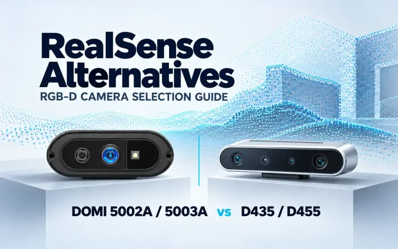
For a compact USB RGB-D design, DOMI’s DM-RGBD5003A combines ToF depth and color imaging with point-cloud output and depth–RGB registration. This gives host software color information alongside scene geometry for object perception and measurement workflows. Published development options include a C/C++ SDK, a Python wrapper and ROS 1 / ROS 2 packages. Review camera data and development options.
Does ROS 2 support prove a tested RTAB-Map configuration?
A model’s ROS 2 development option identifies a software route to investigate. A tested RTAB-Map configuration also needs the specific firmware, driver, host, stream settings and run evidence. This guide provides general input checks; it does not report a DOMI RTAB-Map test run.
When discussing a configuration, include the ROS 2 distribution, operating system, processor, required streams and camera mode. For a running system, add the relevant message encodings, frame IDs, timestamps and a short description of the symptom. These details help focus the discussion on the interface the application actually consumes.
The RGB-D camera category provides model and development-route context. Share your configuration details with DOMI to discuss camera input requirements.