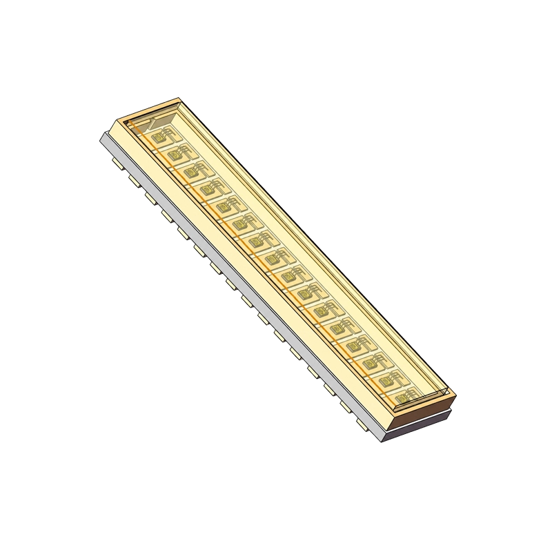
DOMI DMP1KKM 905 nm 16-channel linear VCSEL array in AlN ceramic package
Channels 16-channel linear array
Peak Wavelength 905 nm typ. (895-915 nm)
Peak Power 70 W typ. / 40 W min. per channel

DMP1KKM 905 nm 16-Channel Linear Pulsed VCSEL Array

DMP1KKM is a 905 nm, 16-channel linear VCSEL array in a 17.3 × 4.0 × 1.7 mm AlN ceramic package. Each channel is characterized at 70 W typical peak power with a 15 A, 1.5-2 ns pulse and 0.03% duty cycle at 25 °C.

Key Highlights

  • 70 W typical / 40 W minimum peak optical power per channel
  • 905 nm typical peak wavelength (895-915 nm range)
  • 24° maximum beam divergence using the FW D86 definition
  • 3.0 nm maximum spectral bandwidth
  • 16-channel linear array in an AlN ceramic package
  • Operating-temperature absolute maximum: -20 to 85 °C
Engineering support Datasheet available

Overview

The DMP1KKM is a 905 nm VCSEL emitter built as a 16-channel linear array in an AlN ceramic package measuring 17.3 × 4.0 × 1.7 mm. The datasheet identifies surveillance systems, LiDAR and autopilot, and machine vision systems as target applications.

Each channel is characterized at 25 °C with a 15 A drive current, 1.5-2 ns pulse width and 0.03% duty cycle. At that test point, peak optical power is 70 W typical and 40 W minimum, while peak wavelength is 905 nm typical across a specified 895-915 nm range. These are per-channel pulsed measurements, not total-array output or continuous-wave ratings.

Use the published package outline, recommended pad pattern and circuit diagram for PCB integration. System range, accuracy, illumination uniformity, receiver compatibility, thermal performance and laser-safety classification are not specified in this datasheet and must be validated in the complete product.

Core Engineering Features

Per-channel pulsed optical output

The electro-optical table specifies 70 W typical and 40 W minimum peak power per channel at 15 A, 1.5-2 ns and 0.03% duty cycle. The same operating point gives 20.5 V typical forward voltage, 4.9 W/A typical slope efficiency and 0.7-0.9 Ω series resistance as published.

Defined 905 nm optical envelope

Peak wavelength is specified from 895 to 915 nm with a 905 nm typical value. Maximum spectral bandwidth is 3.0 nm and maximum beam divergence is 24° using the datasheet’s full-width D86 definition, all under the stated per-channel pulse condition.

16-channel AlN ceramic package

The 17.3 × 4.0 × 1.7 mm package combines a 16-channel line-array format with an AlN ceramic construction. The mechanical drawing specifies ±0.2 mm tolerance and includes a recommended PCB pad pattern plus a numbered 1-16 circuit diagram.


Channels
16-channel linear array
Peak Wavelength
905 nm typ. (895-915 nm)
Peak Power
70 W typ. / 40 W min. per channel
Package
17.3 × 4.0 × 1.7 mm AlN

Applications

The following application categories are listed in the DMP1KKM specification. Final optical, electrical, thermal and safety performance depends on the complete system design.

LiDAR and Autopilot Systems

  • The datasheet explicitly identifies LiDAR and autopilot as target applications.
  • Use the per-channel 905 nm wavelength, pulsed output and D86 beam-divergence limits as emitter inputs; validate range, receiver pairing and eye safety at system level.

Surveillance Systems

  • Surveillance systems are a specified application category for the DMP1KKM.
  • The 895-915 nm wavelength range and 3.0 nm maximum spectral bandwidth provide defined inputs for illuminator and receiver-filter evaluation.

Machine Vision Systems

  • Machine vision systems are listed in the product specification.
  • The 16-channel line-array architecture can be evaluated for designs that require spatially segmented pulsed illumination; channel timing and illumination uniformity remain system-design tasks.

Technical Specifications

Electro-optical values below apply to each channel at T = 25 °C. Min, Typ and Max designations are reproduced from Rev. 1.0 of the product specification.

Electro-Optical Characteristics – Each Channel

ParameterSymbolTest ConditionMinTypMaxUnit
Peak WavelengthλpIf = 15 A, 1.5-2 ns pulse width, 0.03% DC895905915nm
Operating CurrentIf1.5-2 ns pulse width, 0.03% DC–15–A
Threshold CurrentItc1.5-2 ns pulse width, 0.03% DC–0.4–A
Forward VoltageVfIf = 15 A, 1.5-2 ns pulse width, 0.03% DC–20.530V
Peak PowerΦeIf = 15 A, 1.5-2 ns pulse width, 0.03% DC4070–W
Beam Divergence (FW D86)1θIf = 15 A, 1.5-2 ns pulse width, 0.03% DC––24deg
Spectrum BandwidthΔλIf = 15 A, 1.5-2 ns pulse width, 0.03% DC––3.0nm
Slope EfficiencyηIf = 15 A, 1.5-2 ns pulse width, 0.03% DC–4.9–W/A
Series ResistanceOhmIf = 15 A, 1.5-2 ns pulse width, 0.03% DC–0.7-0.9–Ω
Reverse CurrentIRIf = 15 A (as published)––10µA
Note 1: Full-width D86 is defined as twice the angle between the propagation direction and the radius from the beam axis containing 86% of total emitter power.

Absolute Maximum Ratings

Absolute maximum ratings are stress limits and are not recommended operating conditions.

ParameterSymbolValueCondition / Note
Operating TemperatureTOPR-20 to 85 °CAbsolute maximum rating
Storage TemperatureTstg-40 to 110 °CAbsolute maximum rating
Forward Current – Pulsed OperationIFP30 ATp = 2.0 ns; DC = 0.03%; TS = 25 °C; per channel
ESD Withstand Voltage – HBMESD4 kVHuman Body Model
Soldering TemperatureTSTG260 °CSymbol reproduced as published
Reverse Breakdown VoltageVr50 VAbsolute maximum rating

Package and PCB Integration

  • Package: AlN ceramic, 17.3 × 4.0 × 1.7 mm.
  • Mechanical tolerance: ±0.2 mm unless otherwise indicated in the drawing.
  • Channel arrangement: 16-channel linear array; the circuit diagram numbers channels 1 through 16.
  • PCB footprint: Use the recommended pad-pattern dimensions in the datasheet; verify land pattern, stencil design and polarity against the released production drawing before layout release.

Reflow and Handling

Pb-Free SnAgCu Reflow Profile

Profile FeaturePublished Limit
Preheat / Soak150-200 °C for 60-120 seconds
Ramp-Up Rate – TL to Tp3 °C/s maximum
Liquidus Temperature and Time Above TL217 °C for 60-150 seconds
Peak Package Body Temperature260 °C
Time Within 5 °C of Actual Peak Temperature30 seconds
Ramp-Down Rate – Tp to TL6 °C/s maximum
Time from 25 °C to Peak Temperature8 minutes maximum

ESD, EOS and Surge Controls

  • The VCSEL is sensitive to electrostatic discharge and electrical overstress even though the absolute-maximum table specifies 4 kV HBM withstand voltage.
  • Equip the drive circuit with surge protection and keep equipment and personnel properly grounded during installation and use.
  • Use an ESD-controlled production environment with appropriate ionization, antistatic clothing, wrist straps, mats, footwear and containers.

FAQs

Does the DMP1KKM deliver 70 W peak power per channel?

Yes. The datasheet specifies 70 W typical and 40 W minimum peak optical power for each channel at T = 25 °C, If = 15 A, a 1.5-2 ns pulse width and 0.03% duty cycle. It does not specify total-array optical output.

Does the DMP1KKM combine 16 channels with 905 nm emission?

Yes. DMP1KKM is a 16-channel linear VCSEL array. Peak wavelength is 905 nm typical, with a specified 895-915 nm range per channel at the published pulse test condition.

Is the DMP1KKM suitable for LiDAR and machine vision?

Yes. The product specification lists LiDAR and autopilot, machine vision systems and surveillance systems as target applications. Range, accuracy, receiver compatibility, illumination uniformity and eye safety must still be validated in the complete system.

Does the DMP1KKM support nanosecond pulsed operation?

Yes. Its electro-optical characteristics are specified at a 1.5-2 ns pulse width and 0.03% duty cycle. The absolute maximum forward-current rating is 30 A per channel at Tp = 2.0 ns, DC = 0.03% and Ts = 25 °C; this limit is not a recommended operating point.

Can the DMP1KKM be integrated with Pb-free reflow assembly?

Yes. The datasheet provides a Pb-free SnAgCu profile with a 260 °C peak package-body temperature, 217 °C liquidus temperature and the published ramp and dwell limits. The device remains ESD/EOS sensitive, so grounded handling, surge protection and an ESD-controlled production environment are required.

Need help integrating DMP1KKM?

Get expert guidance from our sensing engineers on product selection, evaluation samples, system integration, and technical requirements for your application.

You May Also Like

DMP300KP

View Details

DMP200W

View Details

DMP20S

View Details