

Laser module integration: evaluate the TO56 CAN package, external current driver and monitor-PD interface for a 405 nm CW light-source assembly. Confirm the required output at your actual case temperature.
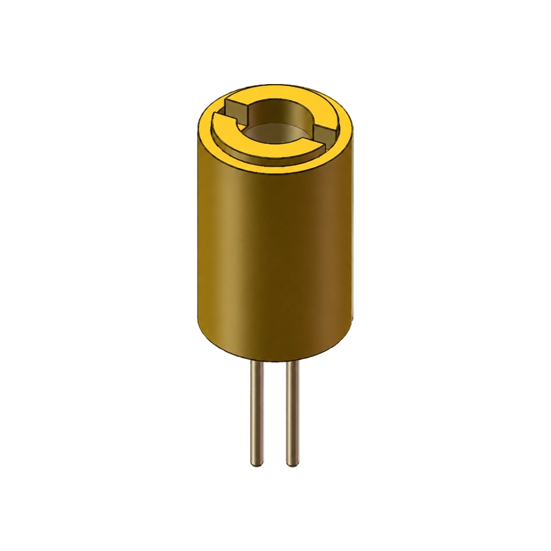
Peak Wavelength
405 nm typ. (40 mA CW, Tc = 25 °C)
Optical Output
18 mW typ. (40 mA CW, Tc = 25 °C)
Package
TO56 CAN; 3-pin LD / PD interface
DMP20S 405 nm TO56 Violet Laser Diode Module
A compact 405 nm laser source with 18 mW typical CW output at 40 mA and Tc = 25 °C. The TO56 CAN package includes a monitor photodiode for external feedback evaluation. Review the electrical limits, beam data and three-pin interface before integration.
Engineering support
Datasheet available
Overview
DMP20S is a 405 nm violet laser diode module in a TO56 CAN package, with 18 mW typical continuous-wave (CW) optical output at 40 mA forward current and a case temperature of 25 °C. It includes a monitor photodiode (PD); the specified monitor current is 0.1-0.5 mA, with a typical value of 0.2 mA, at the same operating point.
For component selection, the key optical values are a 400/405/410 nm minimum/typical/maximum peak wavelength and 3° typical beam divergence labeled D86. These are component-level specifications, not guarantees of system resolution, wavelength stability or closed-loop power stability.
Device classification: the reference specification identifies a 405 nm laser in a TO56 CAN package, but does not state a VCSEL or edge-emitting architecture. Confirm the emitter technology if it is a design requirement.
Technical source: DMP20S Laser Product Specification, Rev. 1.1, 6 March 2023. Features and applications: p. 2; electrical and optical data: p. 3; outline and pinout: p. 4; handling precautions: p. 5.
- Peak Wavelength
- 405 nm typ. (40 mA CW, Tc = 25 °C)
- Optical Output
- 18 mW typ. (40 mA CW, Tc = 25 °C)
- Package
- TO56 CAN; 3-pin LD / PD interface
- Monitor Current
- 0.2 mA typ. (40 mA CW, Tc = 25 °C)
Applications
The datasheet lists laser modules, LiDAR and general applications. The following integration considerations are engineering guidance; application-level performance is not specified.
LiDAR development: LiDAR is a listed application, but no range, timing accuracy, modulation bandwidth, pulse width or peak-pulse rating is supplied. Check compatibility with the intended ranging architecture before selection.
General optical evaluation: use the documented wavelength, power and D86 divergence as initial selection inputs. Fluorescence, triangulation, exposure and other wavelength-dependent uses require separate optical and application validation.
405 nm fluorescence excitation: evaluate DMP20S as an excitation source for compact fluorescence instruments, such as chlorophyll-a water-quality sensing prototypes. Suitability depends on fluorophore absorption, sample geometry, optical attenuation, excitation-rejection filters, detector sensitivity and calibration; no detection limit or system-level performance is specified.
Technical Specifications
Electro-optical characteristics
Test temperature: Tc = 25 °C (case temperature). Rows specify If = 40 mA, CW unless the test-condition cell is blank in the source. A dash means not specified, not zero. Typical values are not guaranteed minimum or maximum values.
| Parameter | Symbol | Test condition | Min | Typ | Max | Unit |
|---|---|---|---|---|---|---|
| Peak wavelength | λp | If = 40 mA, CW | 400 | 405 | 410 | nm |
| Threshold current | Ith | – | – | 15 | – | mA |
| Operating voltage | Vop | If = 40 mA, CW | – | 4.8 | 5.6 | V |
| Laser power | Lp | If = 40 mA, CW | – | 18 | – | mW |
| Slope efficiency | SE | If = 40 mA, CW | – | 1.0 | – | W/A |
| Beam divergence (D86) | θ | If = 40 mA, CW | – | 3 | – | ° |
| Monitor current | Im | If = 40 mA, CW | 0.1 | 0.2 | 0.5 | mA |
Interpretation: 400-410 nm is the peak-wavelength range at the stated test condition, not spectral linewidth or thermal drift. The 3° D86 value is not identified as full-angle or half-angle; no beam circularity, M² or astigmatism specification is provided. Slope efficiency is not wall-plug efficiency and should not be used to extrapolate a guaranteed power-versus-current curve.
Absolute maximum ratings
| Parameter | Symbol | Published limit |
|---|---|---|
| Operating case temperature | TOPR | -20 to +70 °C |
| Storage temperature | Tstg | -40 to +85 °C |
| Maximum reverse voltage | VRL | 2 V |
| Soldering temperature / exposure | Tsg | 260 °C for less than 5 s |
Absolute maximum ratings are limits, not recommended operating targets. The datasheet does not provide a maximum forward-current rating, power derating curve or pulse rating. The 40 mA test current is not a stated current limit; 5.6 V is the maximum operating-voltage entry at the test point, not the reverse-voltage rating or a supply-voltage recommendation.
Package and Pinout
The package feature is TO56 CAN. Use the actual outline drawing for mechanical design instead of assuming dimensions from the package family name.
| Drawing item | Dimension / note |
|---|---|
| Body diameter | Ø5.90 ±0.1 mm |
| Body height, excluding leads | 8.80 mm; drawing annotation: ±1 mm |
| Lead diameter | Ø0.45 ±0.1 mm |
| Bottom-view pin-circle callout | Ø2 mm; not a 2 mm adjacent-pin pitch |
| Unmarked tolerances | ±0.1 mm |
Three-pin connection, bottom view
| Pin | Drawing label | Connection shown |
|---|---|---|
| 1 | PD | Monitor photodiode terminal; anode in the drawn schematic |
| 2 | CASE | Case-connected common node; both cathodes in the drawn schematic |
| 3 | LD | Laser diode terminal; anode in the drawn schematic |
The schematic shows an LD and a monitor PD, not an integrated driver or APC controller. Confirm PD bias, monitor-current polarity and driver compatibility before wiring. The feature wording “Calibrated Laser” does not define a lens assembly, calibration accuracy, traceability or a calibration certificate.
Integration Notes
The precautions below separate the supplier’s stated handling requirements from engineering checks needed for a complete system.
- Drive and transient control: use a suitable current-regulated laser driver and review start-up, shutdown and fault transients. The supplier requires surge protection and warns that ESD and electrical overstress can damage the laser (p. 5). Do not treat 4.8 V as a fixed-voltage drive instruction.
- Monitor PD and external APC: the PD signal can be evaluated as feedback for an external automatic power control circuit. Characterize the monitor-to-output relationship, bias conditions, loop stability and fault response; no APC accuracy or lifetime stability is specified.
- Thermal and optical validation: manage case temperature and validate performance away from Tc = 25 °C. Request L-I-V curves, spectral data, the D86 measurement definition and beam profiles if your design depends on power tracking, a focused spot or angular coverage.
- Assembly and ESD: follow the 260 °C / less-than-5-second soldering limit. The supplier calls for grounded personnel and equipment, ion blowers and appropriate antistatic handling materials (p. 5). The stated limit is not a complete reflow-process qualification.
- Laser safety review: arrange a qualified assessment of the completed optical assembly, including beam access, reflections, enclosure and appropriate protective measures. This datasheet provides no certified laser class, eye-safety claim or regulatory approval for an end product.
FAQs
Does the monitor photodiode provide built-in automatic power control?
The monitor photodiode is shown in the package schematic, and Im is 0.1/0.2/0.5 mA minimum/typical/maximum at If = 40 mA, CW and Tc = 25 °C. No APC circuit is documented. Any closed-loop power control needs an external driver and validation of the PD interface.
What is the DMP20S pinout?
In the datasheet bottom view, pin 1 is PD, pin 2 is CASE and pin 3 is LD. The drawn diode symbols connect both cathodes to pin 2; pins 1 and 3 are the PD and LD anodes respectively. Confirm the drawing orientation, PD bias and case connection before powering the device.
Does the -20 to +70 °C range guarantee 18 mW output?
No. That range is an operating case-temperature entry in the absolute maximum ratings. The 18 mW typical output is specified at Tc = 25 °C and If = 40 mA, CW. No output-power derating curve or full-temperature power guarantee is provided.
Resources and RFQ
Review the DMP20S datasheet (PDF, Rev. 1.1) and send your operating requirements for a configuration review and quotation. Pricing, MOQ, lead time and sample availability are subject to confirmation.
- Optical requirementsRequired wavelength window and power, CW or intended modulation, working distance, beam or spot requirements, and acceptance criteria.
- Electrical and mechanical fitDriver topology and supply, monitor-PD/APC plan, case-temperature range, mounting constraints and pinout confirmation.
- Procurement and documentationEvaluation quantity, expected production volume, target schedule, destination market, current drawing and any required qualification evidence.
Need another wavelength, output level or package? Explore all DOMI products or contact the engineering team. Confirm the ordered configuration against the current specification before design release.
You May Also Like
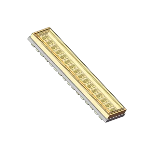
DMP1KKM
Channels
16-channel linear array
Peak Wavelength
905 nm typ. (895-915 nm)
Peak Power
70 W typ. / 40 W min. per channel
Package
17.3 × 4.0 × 1.7 mm AlN
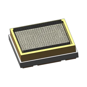
DMP300KP
Wavelength
895-915 nm (905 nm typ.)
Peak Output
300 W typ. @ 61 A, 5 ns
Beam Divergence
40° H × 30° V typ.
Package
5.2 × 5.2 × 1.55 mm AlN
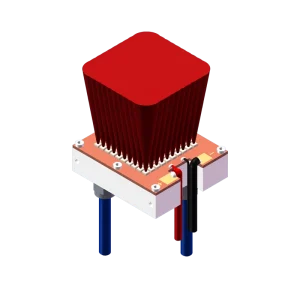
DMP200W
Peak Wavelength
980 nm
Optical Operating Point
200 W CW at Tc = 25 °C
Cooling Water
15-25 °C; ≥10 L/min
Plan-View Outline
75 × 65 mm