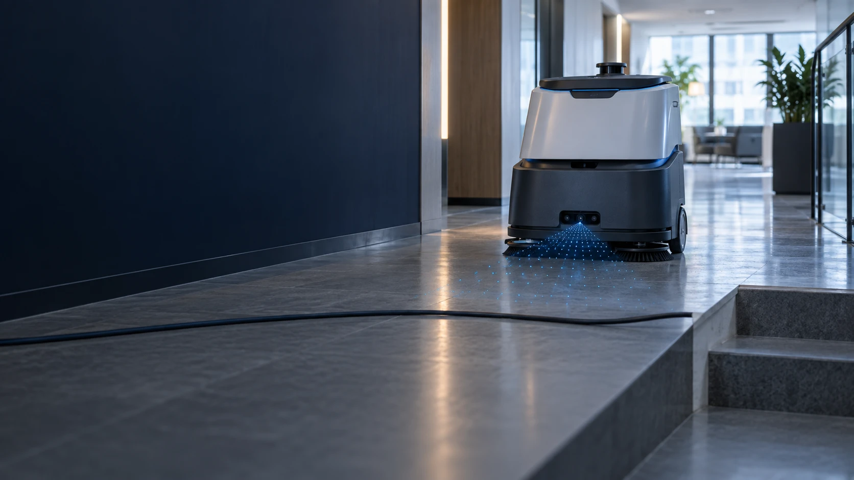
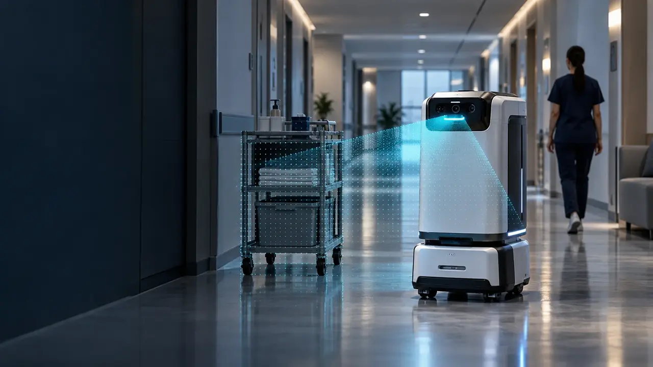
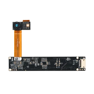
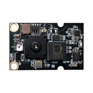
A 2D LiDAR observes geometry at one height. Low cables, floor-level objects, overhangs and drop-offs can sit outside that plane but inside the robot's collision envelope. A 3D ToF or RGB-D camera adds vertical scene coverage so the host system can evaluate geometry closer to the ground, above the scan line and beyond the expected floor plane.
DOMI cameras provide depth-sensing data and integration building blocks. Obstacle classification, cliff logic, path planning, vehicle control and safety-rated functions are implemented and validated in the complete robot system.
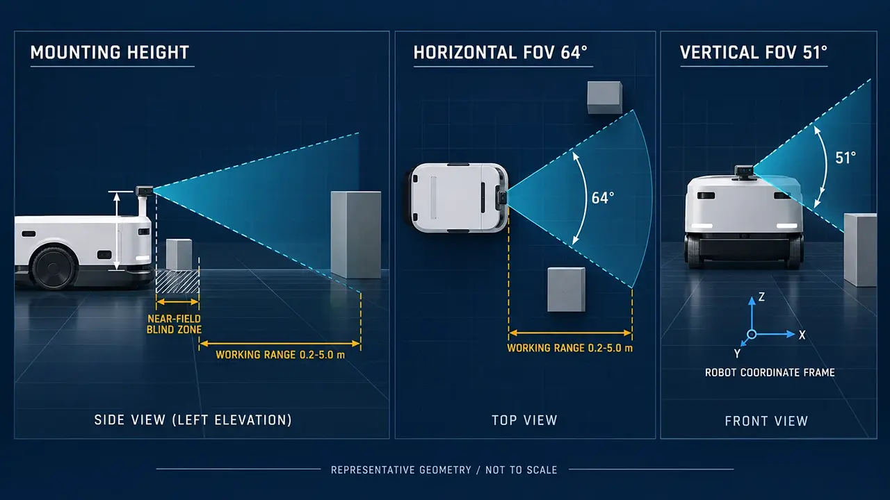
Conceptual geometry. The host system still defines the region of interest, filtering and route decision.
Positive obstacles and drop-offs need different evidence
Positive obstacles rise from an expected ground plane. Negative obstacles interrupt it. The camera supplies depth evidence for both, but the perception application needs separate rules, thresholds and validation cases.
Positive obstacle evidence
Geometry above the expected ground
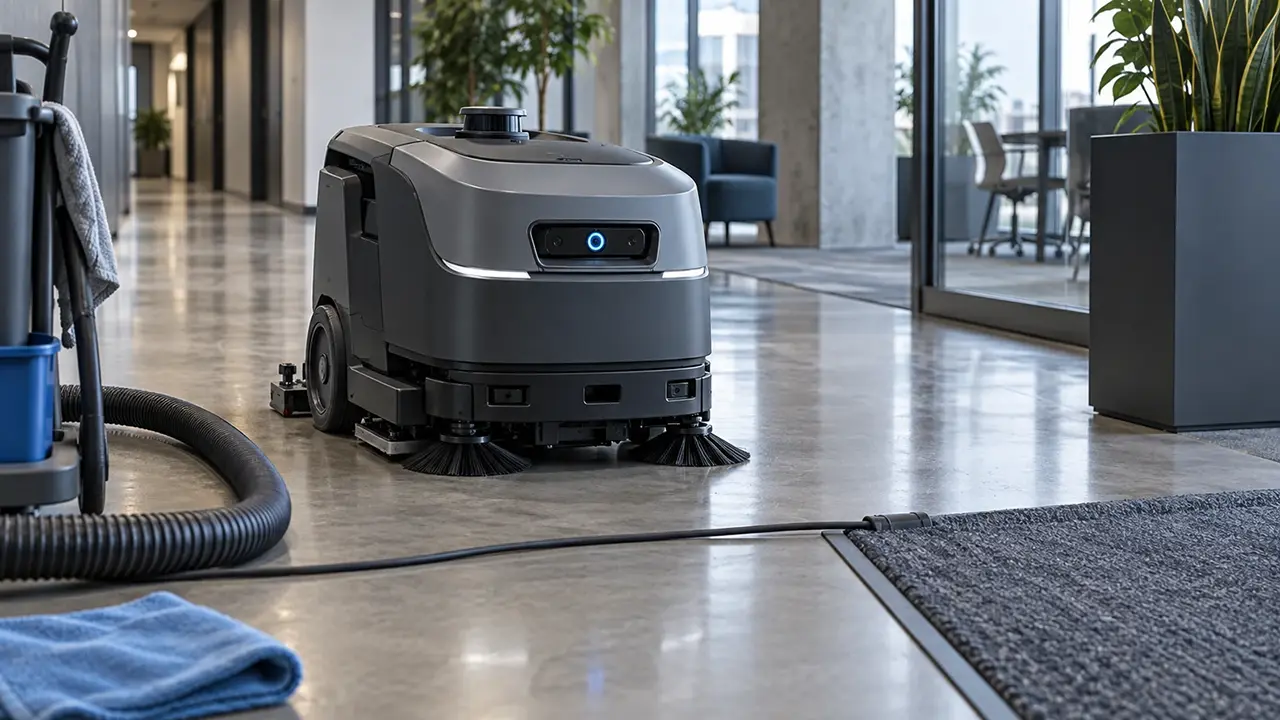
Cables and hosesThin, floor-level objects can sit below a planar scanner while still crossing the wheel or brush path.
Chair legs and crossbarsVertical depth coverage helps expose furniture geometry that does not intersect the primary scan height.
Tools and debrisMops, cartons, floor tools and pallet feet become measurable scene geometry for the host system.
Overhanging edgesTable edges, shelves and suspended objects can enter the robot envelope from above the scan plane.
Low carts and matsLow-clearance objects and floor transitions need evidence close to the ground and near the vehicle.
Negative obstacle evidence
A break in the expected ground
Stair edgesA forward or downward-looking view can reveal where the expected ground plane stops.
Loading-bay dropsA sudden level change can be evaluated as a drop-off when the geometry is inside the configured ROI.
Floor openingsMissing or invalid depth can contribute to an opening decision, but it needs application rules and corroboration.
Ramps and stepsGround-plane estimation should distinguish a traversable slope from a discontinuity that needs a route decision.
Temporary occlusionA single invalid pixel is not proof of a cliff. Track evidence over space and time before acting.
The camera measures geometry. The robot decides what to do.
Treat depth sensing as one layer in a perception and safety architecture. Keep the data boundary visible so the evaluation tests the actual robot behavior, not only a promising frame.
DOMI depth camera
Depth map
IR image
Optional RGB image
Calibration and model-specific validity data
Perception application
Ground and ROI model
Obstacle and drop-off evidence
Filtering and temporal tracking
Robot-frame transformation
Navigation and safety system
Costmap or occupancy layer
Slowdown or reroute
Stop and recovery
Certified safety chain
A standard depth camera is not a certified safety scanner. Use the required safety LiDAR, bumper, emergency stop and control architecture for the target robot and market.
From depth frames to a safer local path
A useful evaluation follows the data through the same coordinate, timing and decision boundaries that the production robot will use.
Capture the route
Acquire synchronized depth, IR and optional RGB from a representative viewpoint.
Validate the depth
Reject or flag low-confidence, saturated or out-of-envelope samples.
Build robot-frame geometry
Apply calibration and transform points into the robot base frame.
Mark obstacle and drop-off evidence
Create positive-obstacle and negative-obstacle evidence for the local map.
Plan, stop or recover
Let the host system select a route action and record the exception.
ROS 2 systems can publish depth-derived geometry as PointCloud2 and use an obstacle or voxel layer in Nav2. The exact driver, topic contract, filtering and cliff logic remain application-specific.
Design around the route the robot actually runs
The smallest useful test object is the one that causes a real stop, reroute or entanglement on the customer route.
Commercial cleaning robots
Reduce avoidable stops and entanglement by evaluating the exact cables, tools, floor finishes and lighting found on the cleaning route.
Cables and hoses
Dark or wet floor finishes
Cleaning tools and debris
Turns and narrow passages
Food delivery and service robots
Add vertical scene coverage where a planar scan cannot represent low crossbars, overhangs and changing floor geometry.
Chair legs and crossbars
Table edges and carts
Door thresholds and steps
People and narrow corridors
Representative DM-RGBD5003A geometry. Not a universal mounting recommendation and not to scale.
Cover the floor before the blind zone reaches the bumper
Choose mounting from the robot geometry backward. The useful view is the overlap between the camera FOV, ground intersection, low-obstacle region, cliff ROI, turning envelope and stopping margin.
Low forward views can cover ground and near-field obstacles.
A second higher view can add overhang and people coverage without sacrificing the bumper zone.
Multiple views need interference, synchronization and bandwidth testing.
Fixed mounting height and pitch should come from the final mechanics and route validation.
Start from stopping distance and FOV, not from a fixed mounting number.
Validate the surfaces that can look like free space
Depth quality is a scene property. Test geometry, optics and system behavior together instead of treating a single invalid return as a complete decision.
Geometry
Thin or partially occluded cables
Oblique stair edges
Ramps and floor transitions
Objects inside the near-field blind zone
Optics
Black carpet and low-reflectivity surfaces
Glossy floors, water films and specular returns
Glass doors and transparent objects
Strong ambient infrared and dirty cover windows
System behavior
Motion blur or vibration
Perception-to-control latency
False obstacles from noisy depth
Multi-camera interference and recovery after occlusion
Invalid depth can mean several different things. Treat it as an input to a validated decision rule, not as automatic proof of a cliff or free space.
Use each sensor where its geometry is strongest
For commercial cleaning and delivery robots, the practical architecture is usually sensor fusion. A depth camera adds vertical geometry to the localization and safety sensors already on the platform.
Sensor paths, useful contributions and questions to validate for robot obstacle avoidance
Sensor path
Useful contribution
Questions to validate
3D ToF or RGB-D camera
Dense near-field depth across a vertical field of view, with optional appearance cues.
Range, pixel coverage, reflectivity, ambient IR, multi-path and active-light interference.
2D LiDAR or safety scanner
Planar localization, long horizontal coverage and safety options on applicable products.
Scan-plane blind spots and whether off-plane obstacles enter the vehicle envelope.
Stereo depth camera
Passive 3D geometry with different range and resolution tradeoffs.
Texture, lighting, baseline, compute and close-range completeness.
Ultrasonic or proximity sensor
A low-cost near-field or material-independent complement in selected scenes.
Beam width, angular resolution, surface angle, update rate and interference.
Bumper or contact edge
Last-resort contact confirmation at the physical boundary.
Contact force, coverage, recovery and the safety architecture.
3D ToF or RGB-D camera
Useful contribution
Dense near-field depth across a vertical field of view, with optional appearance cues.
Questions to validate
Range, pixel coverage, reflectivity, ambient IR, multi-path and active-light interference.
2D LiDAR or safety scanner
Useful contribution
Planar localization, long horizontal coverage and safety options on applicable products.
Questions to validate
Scan-plane blind spots and whether off-plane obstacles enter the vehicle envelope.
Stereo depth camera
Useful contribution
Passive 3D geometry with different range and resolution tradeoffs.
Questions to validate
Texture, lighting, baseline, compute and close-range completeness.
Ultrasonic or proximity sensor
Useful contribution
A low-cost near-field or material-independent complement in selected scenes.
Questions to validate
Beam width, angular resolution, surface angle, update rate and interference.
Bumper or contact edge
Useful contribution
Last-resort contact confirmation at the physical boundary.
Questions to validate
Contact force, coverage, recovery and the safety architecture.
Choose the camera from the obstacle envelope backward
Start with a platform that makes route data easy to collect, then compare USB and embedded paths against the final mechanical and software envelope.
Main evaluation platform
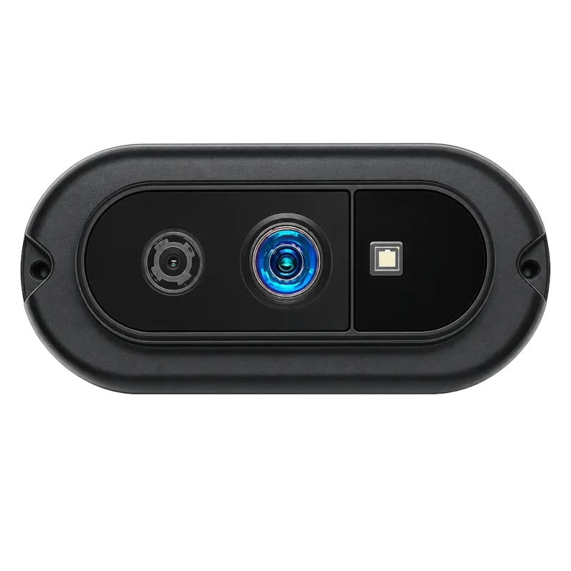
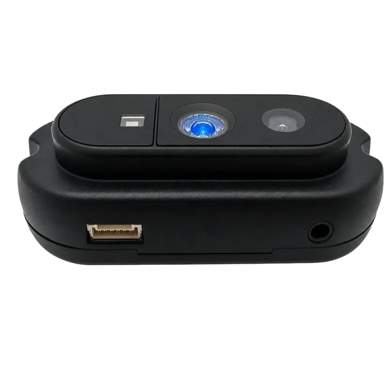
DM-RGBD5003A
Dataset capture, algorithm proof of concept and ROS integration evaluation. Use its depth, RGB and registered point-cloud path to understand the actual route before committing to a production envelope.
Depth
Up to 640 x 480 at 25 fps
RGB
Up to 1280 x 960 at 30 fps
Published range
0.2-5.0 m
ToF FOV
64° H x 51° V
Interface
USB 2.0
Software path
ROS1, ROS2, C/C++, Python, OpenCV and PCL
Confirm the required ROS distribution, driver release, strong-light behavior and complete-system latency during evaluation.
Algorithm validation and full-feature ground plus overhang obstacle sensing
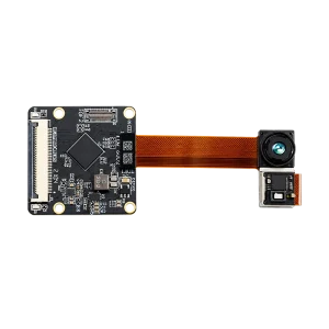
Embedded cleaning robot and near-ground small obstacles
Compact USB obstacle-avoidance module
Ultra-wide-angle cliff and drop-off edge warning
Resolution and frame rate
640 x 480 @ 25 fps
320 x 240 @ 30 fps
320 x 240 @ 30 fps
100 x 100 @ 20 fps
Field of view (H x V)
64° x 51°
71.8° x 56.6°
Custom
60° x 60°
Wavelength for ambient-light tolerance
940 nm / 850 nm
940 nm
850 nm / 940 nm
940 nm
Typical cable detection reference
5 mm cable at 1.2 m
5 mm cable at 0.8 m
Basic obstacle avoidance
Coarse obstacle detection only
Primary host interface
USB 2.0 (UVC)
MIPI CSI-2 (2-lane)
USB 2.0
UART / SPI
Wavelength, range, environmental behavior, output format and cable performance are configuration and model specific. Treat the cable values as evaluation references, then validate pixel coverage on the real cable, floor, lighting and mounting geometry before selecting a production path.
Turn a route risk into a repeatable test
A staged evaluation makes the acceptance criteria specific to the robot, route and safety architecture.
Define the operating envelope
Robot speed, stopping distance, minimum target size, floor materials, light and drop geometry.
Thin cables, crossbars, dark floors, reflective surfaces, turns, occlusion and full vehicle speed.
Validate the complete behavior
Detection, tracking, map update, slowing, stop, reroute, recovery and fault handling.
Acceptance metrics to define
Set target values with the customer team. Do not infer them from a camera datasheet.
Detection recall by obstacle class
False-obstacle rate per route hour or distance
Cliff-edge localization error
Time to first valid detection
Perception-to-control latency
Minimum stopping margin
Valid-depth coverage in each ROI
Recovery success after temporary occlusion
Performance across light, floor and contamination conditions
Questions engineers ask before route testing
Short answers about cables, drop-offs, sensor fusion, mounting and the boundary between camera data and robot behavior.
Can a ToF camera detect thin cables on the floor?
Yes, when the cable occupies enough valid pixels at the selected distance and angle. Detection also depends on diameter, reflectivity, occlusion, motion and the decision threshold. Test the actual cable, floor finish and robot speed. A camera observation still needs host-side classification, tracking and route behavior.
How does a depth camera detect a cliff or stair edge?
It compares measured depth with the expected ground geometry in a configured region of interest. A drop-off can be supported by a ground-plane interruption, a downward depth change or a pattern of invalid samples. It is not safe to treat one invalid pixel as proof of a cliff. Validate the complete rule on real steps and ramps.
Can a 3D depth camera replace the robot's 2D LiDAR?
No, not by default. A depth camera adds vertical near-field geometry, while 2D LiDAR can provide planar localization, longer horizontal coverage or a safety-rated function on applicable products. The right architecture depends on geometry, range, lighting, stopping distance and the required safety chain. Sensor fusion is often the practical path.
Is a DOMI camera a safety-rated obstacle sensor?
No. DOMI cameras provide depth-sensing data and integration building blocks. Obstacle classification, cliff logic, path planning, vehicle control and safety-rated functions are implemented and validated in the complete robot system. Use the required safety LiDAR, bumper, emergency stop and control architecture for the target robot and market.
What camera resolution and field of view should I start with?
It depends on the smallest target, working range, mounting height, pitch, stopping distance and the amount of the route that must be covered. Start with a representative RGB-D platform for data capture, then compare pixel coverage and blind zones against embedded candidates. Confirm the final geometry in route testing.
How do dark, reflective or wet floors affect ToF depth?
They can reduce returned signal or create displaced, noisy or missing depth. Wet and glossy surfaces can also add specular returns. Test the real floor and target materials at the range, angle, ambient infrared and motion conditions that matter. Define invalid-depth handling and a sensor-fusion response before release.
Where should the camera be mounted on a cleaning or delivery robot?
Mounting should be selected from the obstacle envelope and stopping distance backward. A lower forward view can cover the ground and near-field obstacles, while another viewpoint may help with overhangs or people. Validate optical center, pitch, FOV, bumper blind zone, turning envelope, cover window and camera-to-base calibration in the final mechanics.
Can multiple ToF cameras interfere with each other?
They can in some layouts because overlapping active illumination may create interference. Evaluate camera placement, field overlap, synchronization, exposure, USB bandwidth and host processing as one system. Do not assume that identical cameras will behave independently when their fields of view overlap on the route.
Does DOMI provide ROS 2 drivers or a complete obstacle avoidance algorithm?
Not by itself. The published DM-RGBD5003A path includes ROS1, ROS2, C/C++, Python, OpenCV and PCL development routes. Confirm the selected model, driver release, ROS distribution, topic contract and output fields during evaluation. Obstacle extraction, cliff logic, costmap updates, planning and safety behavior remain application-specific.
Plan your obstacle evaluation
Find the right sensing path for your robot's route
Share the obstacle geometry, route conditions and robot integration requirements. Our team will help compare a practical camera and validation path.
Camera and FOV fit for the robot's obstacle envelope
Validation priorities for cables, floors, cliffs and ambient light
A clear path from depth data to the host perception stack
Tell us what your robot needs to detect
A few details are enough to start the conversation.