

Locate the pallet and fork pockets
Use depth geometry to identify pallet position and pocket regions within the camera view.
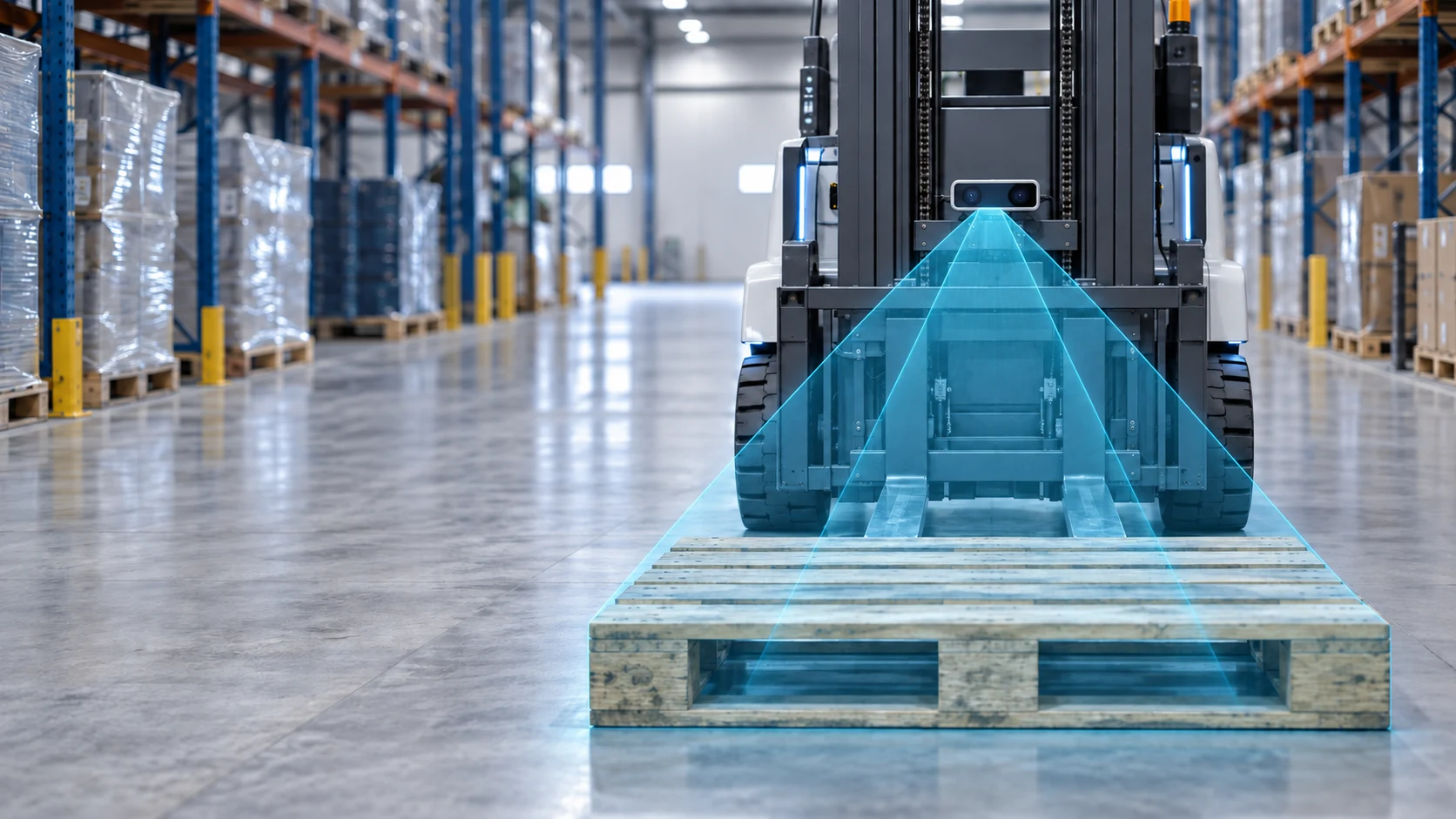
Give autonomous forklifts depth data for pallet pose estimation, fork-pocket localization and closed-loop approach.
Use depth geometry to identify pallet position and pocket regions within the camera view.
Provide spatial data for calculating pallet offset, orientation and approach corrections.
Feed updated perception data into the host system during alignment, approach and pickup validation.
DOMI supplies the depth-sensing layer. Your application or system integrator turns those observations into pallet decisions, vehicle actions and recovery logic.
DOMI camera provides
Your application system implements
Safety-rated functions must be implemented and validated within the vehicle's certified safety architecture.
The camera supports each handoff. The host system decides what the next action means and when the vehicle should retry or stop.
Find the pallet geometry in the current camera view.
Identify the left and right fork-pocket regions.
Calculate position and orientation relative to the camera.
Use updated offsets to correct the approach trajectory.
Move through the insertion step under vehicle control.
Validate pickup state or return to a defined retry path.
Reliable docking depends on perception quality, calibration, mounting geometry, control strategy and validation under the target operating conditions.
Pallet geometry, surface properties, occlusion, ambient light and mounting position can all affect the available depth data. Evaluation should reproduce the target operating environment.
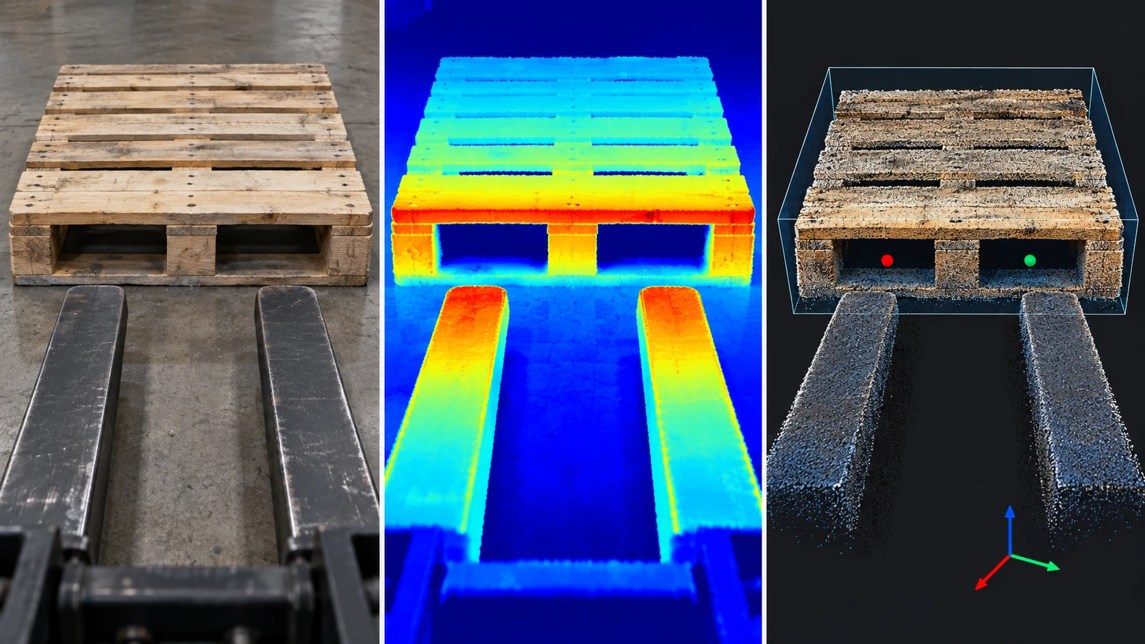
Check pose estimation when the pallet is not square to the vehicle.
Test how missing boards, bent runners and irregular edges affect detection.
Reproduce blocked pockets, loads and nearby objects from the operating aisle.
Measure valid depth and define a response for ambiguous returns.
Include low-return surfaces at the distances and angles that matter.
Validate the depth signal across the real indoor or semi-outdoor light range.
Optical and motion qualification
Pallet docking is a close-range, reflective and moving perception problem. Qualify the physical sensing envelope before tuning the application algorithm.
Pallet pockets are concave optical cavities. Reflections can distort depth at corners, so check valid-depth or confidence behavior, edge filtering and repeatability with representative pocket geometry. Product-specific anti-MPI behavior must be confirmed with DOMI.
Compare emitted power, sensor response, ambient infrared, target reflectivity and working range in the real scene. Do not transfer the published range of one wavelength configuration to another.
The listed options begin around 0.2-0.3 m. Characterize the final insertion distance and near-field behavior, and consider an independent proximity or limit signal for terminal stop logic.
Frame rate is not end-to-end control latency. Qualify vibration, exposure behavior, host timestamps and motion during the 10-30 fps path. Confirm hardware trigger or multi-camera sync for the selected module.
Choose from the scene geometry and result you need, not from the sensor label alone. The comparison below frames the engineering questions to bring into evaluation.
| Technology | Why teams consider it | Docking questions to qualify |
|---|---|---|
| 3D ToF | Dense per-pixel depth for near-field geometry and low-texture surfaces. | Ambient infrared, reflectivity, multi-path effects and near-field range. |
| Stereo vision | Depth from correspondence when texture, baseline and lighting support matching. | Low-texture wood or plastic, occlusion, baseline and compute budget. |
| 3D LiDAR | Longer-range spatial context with a different density, scan and integration tradeoff. | Pocket-edge coverage, close-range behavior, scan timing and vehicle latency. |
Working distance, optical coverage and coordinate frames shape the quality of the docking data before any algorithm runs.
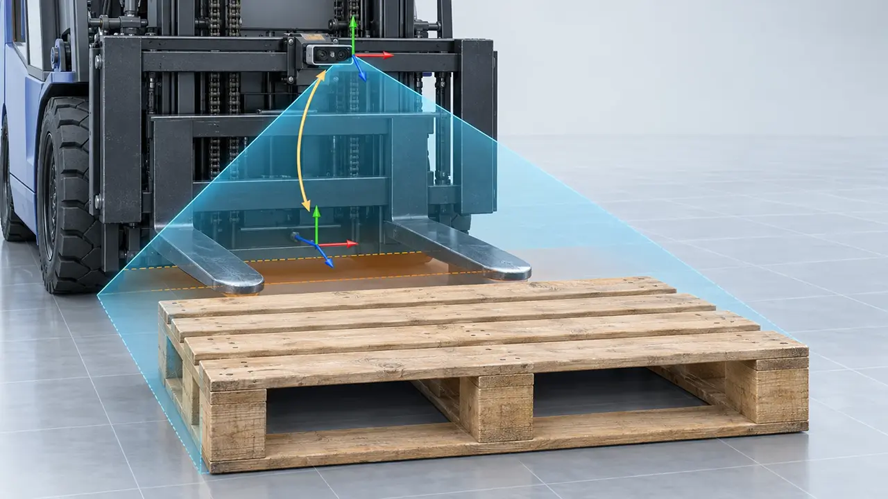
Define the minimum and maximum distance from the camera to the pallet and pockets.
Cover the pallet width and approach envelope without wasting pixels outside the task.
Confirm that pocket edges and depth changes are represented at the target range.
Compare mast-mounted, fork-carriage mounted and over-the-fork positions, then qualify the camera-to-fork coordinate transform.
Match outputs, bandwidth, SDK path and processing platform to the vehicle architecture.
Start with one representative platform, then compare the interface and optics against the production envelope.
| Evaluation role | Model | Wavelength | Published range | Interface | Output or integration focus |
|---|---|---|---|---|---|
| Algorithm POC and dataset | DM-RGBD5003A | 940nm | 0.2-5.0 m | USB 2.0 | RGB, depth and registered point cloud. Check ROS / ROS 2 version requirements. |
| USB depth integration | DM5005A | 850 nm or 940 nm | 0.3-5 m at 850 nm; 0.2-2 m at 940 nm | USB 2.0 / UVC 1.2 | Point Cloud, Depth and IR output |
| Indoor embedded OEM | DMOM2808D | 850 nm | 0.25-4.5 m | MIPI CSI-2, 2 lanes | 320 x 240 module path. Confirm output mode and calibration flow. |
| Docking and semi-outdoor | DMOM2508CL | 940 nm | 0.2-2.0 m | MIPI | Near-range pocket tracking candidate. Validate light and material conditions. |
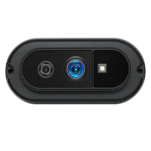 Recommended evaluation platform
DM-RGBD5003A
RGB plus depth for algorithm evaluation
View details
Recommended evaluation platform
DM-RGBD5003A
RGB plus depth for algorithm evaluation
View details
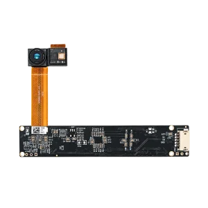 Integration choice
DM5005A
USB depth and IR integration
View details
Integration choice
DM5005A
USB depth and IR integration
View details
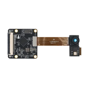 Embedded OEM choice
DMOM2808D
850 nm MIPI module path
View details
Embedded OEM choice
DMOM2808D
850 nm MIPI module path
View details
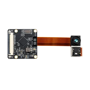 Near-range docking choice
DMOM2508CL
940 nm MIPI module path
View details
Near-range docking choice
DMOM2508CL
940 nm MIPI module path
View details
DMOM2808D and DMOM2508CL are conditional MIPI choices. Compare range, wavelength, field of view and actual light and material conditions before selecting the production module.
Need another RGB-D configuration? Explore DM-RGBD5002A
Published product specifications are a starting point. Confirm strong-light behavior, software versions and project-specific performance during evaluation.
A staged evaluation turns a camera specification into a sensing path your robot team can test and own.
Pallet type such as Euro pallet (EUR 1), GMA, CHEP, block or stringer, plus distance, lighting, speed and mounting constraints.
Match range, field of view, wavelength, output and host interface.
Include nominal pallets and difficult conditions from the real site.
Evaluate detection, calibration, alignment, insertion and exception recovery together.
Short answers to common camera, integration and operating-condition questions.
DOMI cameras provide depth, IR, optional RGB, point-cloud and calibration data. Pallet detection, fork-pocket localization, pose estimation and vehicle control are normally implemented in the customer or system-integrator application.
Start with RGB-D when you need fast data capture, appearance cues and an evaluation path through RGB-D or XYZ point clouds. Choose depth-only when the production design has a clear need for depth, IR, compact integration or a MIPI host path.
Mounting depends on the working distance, field of view, fork geometry, vibration, cover glass and calibration strategy. Use the recommended mounting concept as a starting point, then validate the final camera-to-fork transform on the vehicle.
Pallet geometry, distance, pixel coverage, surface properties, occlusion, ambient infrared, mounting position, calibration and host-system latency all affect the available depth data. Reproduce the target operating envelope during evaluation.
It may be possible, but these conditions must be tested with representative pallets and materials. Define valid-depth thresholds, retry behavior and exception handling in the application rather than assuming every surface will return usable depth.
Depending on the model, the camera can provide depth, IR, optional RGB, registered RGB-D or XYZ point-cloud data, calibration parameters and a model-specific SDK or host interface. Confirm exact outputs in the product documentation.
Pallet fork pockets are concave optical cavities, so multi-path reflections can distort depth at corners. Evaluate the selected module's valid-depth or confidence behavior, edge filtering and repeatability with representative pockets. Product-specific anti-MPI behavior must be confirmed with DOMI.
DOMI product materials list ROS and ROS 2 development paths for representative RGB-D evaluation. Confirm the selected model, ROS 2 distribution, driver or node availability and message contract, including any Humble, Iron, Nav2 or MoveIt requirements, before integration.
Share the pallet type, working distance, vehicle platform, mounting position, lighting, target conditions and preferred interface. DOMI can then help identify a representative camera configuration and a validation path.
Plan your pallet evaluation
Share your pallet type, operating distance and vehicle integration requirements. Our team will help evaluate the camera configuration and validation path.
A few details are enough to start the conversation.