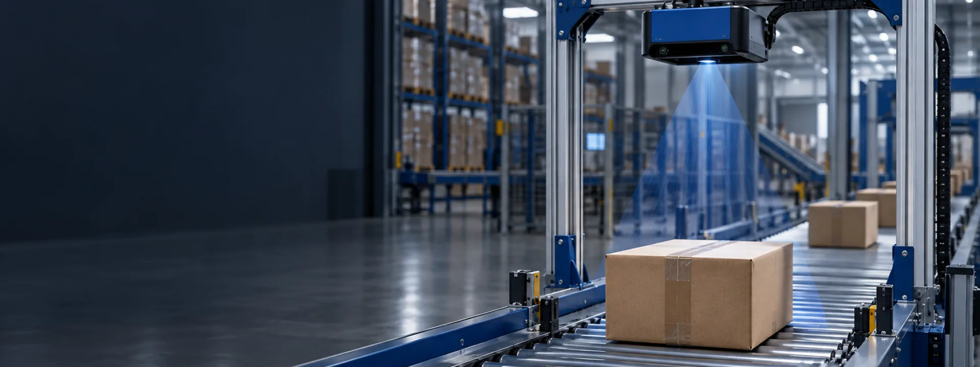
3D ToF cameras for parcel dimensioning and volume measurement
Design static or in-motion box, package and pallet dimensioning with calibrated geometry, auditable point-cloud processing and a DWS/WMS integration path your engineering team can validate.
Recover parcel dimensions from depth data without contact or manual gauges.
Dimensional weight inputs
Return L x W x H and computed volume for downstream volumetric weight rules in the DWS or host system.
Geometry you can audit
Keep the depth map, point cloud, masks and confidence rules that support each measurement.
A practical integration path
Connect camera output to dimensioning, weighing and scanning (DWS), WMS, PLC or edge-compute software through a defined interface.
How it works
How 3D ToF parcel dimensioning works
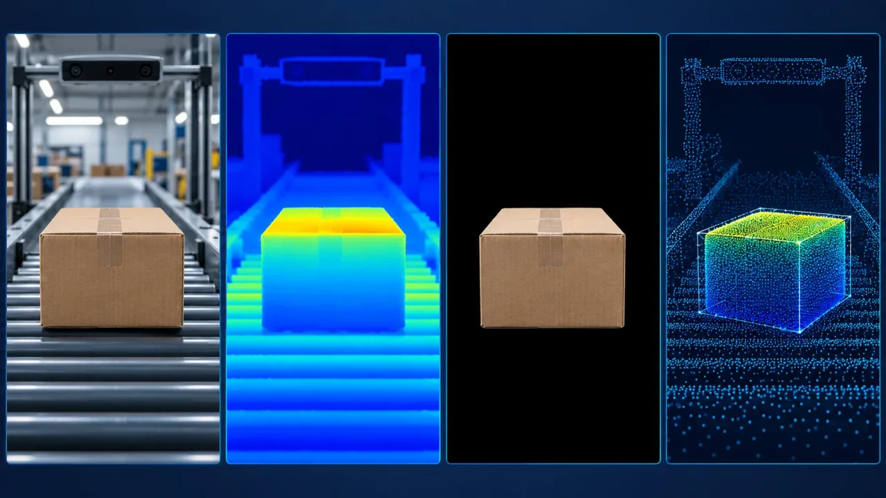
A 3D ToF camera measures distance at each image pixel. Referencing that depth map to a calibrated belt, table or floor plane lets host software isolate the object, fit its occupied envelope, and return length, width, height and volume for cubing, dimensional weight input, sortation or storage planning.
The camera is the depth-sensing layer, not a complete dimensioning, weighing and scanning (DWS) appliance. Scales, code readers, host logic and any legal-for-trade certification remain system-level responsibilities.
Measurement model
A volume result is a calibrated pipeline, not a camera checkbox
The ToF sensor provides depth observations. Your algorithm turns those observations into dimensions, volume, confidence and a decision. Each step should be observable during commissioning.
L
length
W
width
H
height
What the system must return
What a production dimensioning station should return
A robust station does more than publish a number. It records the scene conditions and quality signals that tell your team when the result is valid, when to retry, and when to route an exception.
Dimensions with units
Computed volume
Valid-pixel or point-cloud coverage
Confidence and exception status
Timestamp and trigger ID
Calibration version
Illustrative processing sequence. Keep the raw depth evidence, segmentation result and quality signals alongside each published dimension and volume.
Reference architecture
From a ToF depth map to parcel dimensions and volume
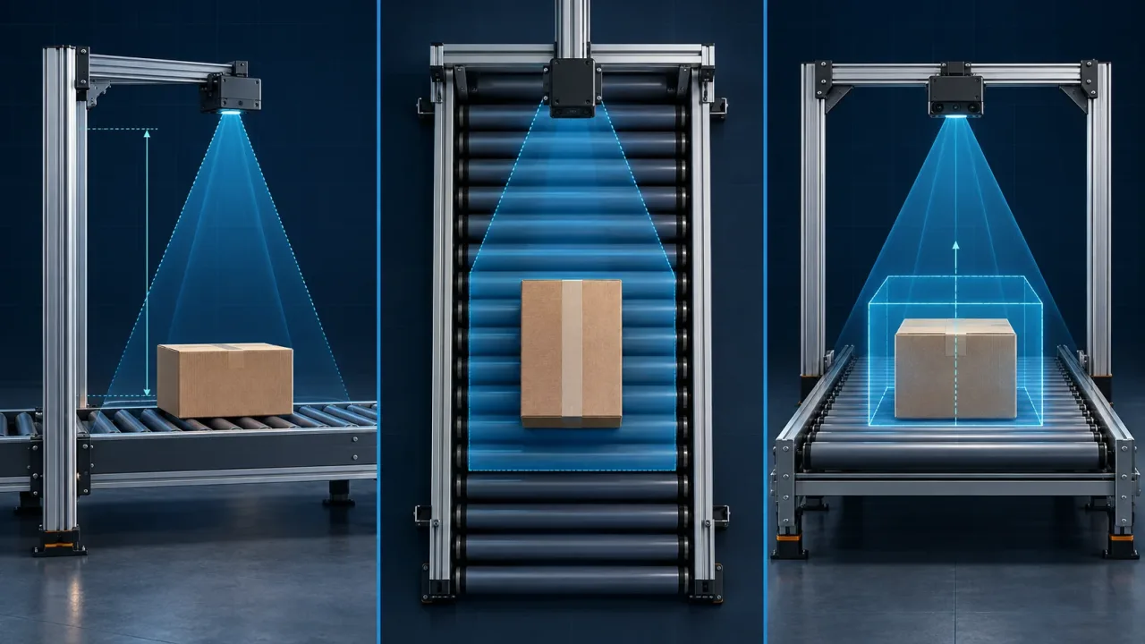
Use this sequence to define interfaces between optics, point-cloud processing, measurement logic and the line-control system.
Illustrative station geometry. Validate mounting height, field of view, near-field clearance and blind zones with the final optics and conveyor mechanics.
01
Capture
The overhead ToF camera samples the parcel, pallet or object surface in a calibrated volume.
02
Segment
Separate the target from the conveyor or background using depth, region and application rules.
03
Fit geometry
Estimate the occupied envelope, top plane, edges or point-cloud shape for the target class.
04
Compute volume
Apply the selected geometry model and return dimensions with quality flags and units.
05
Publish
Send dimensions, volume, image evidence and exception status to the line controller or business system.
Application fit
Match static, conveyor and pallet dimensioning to the object
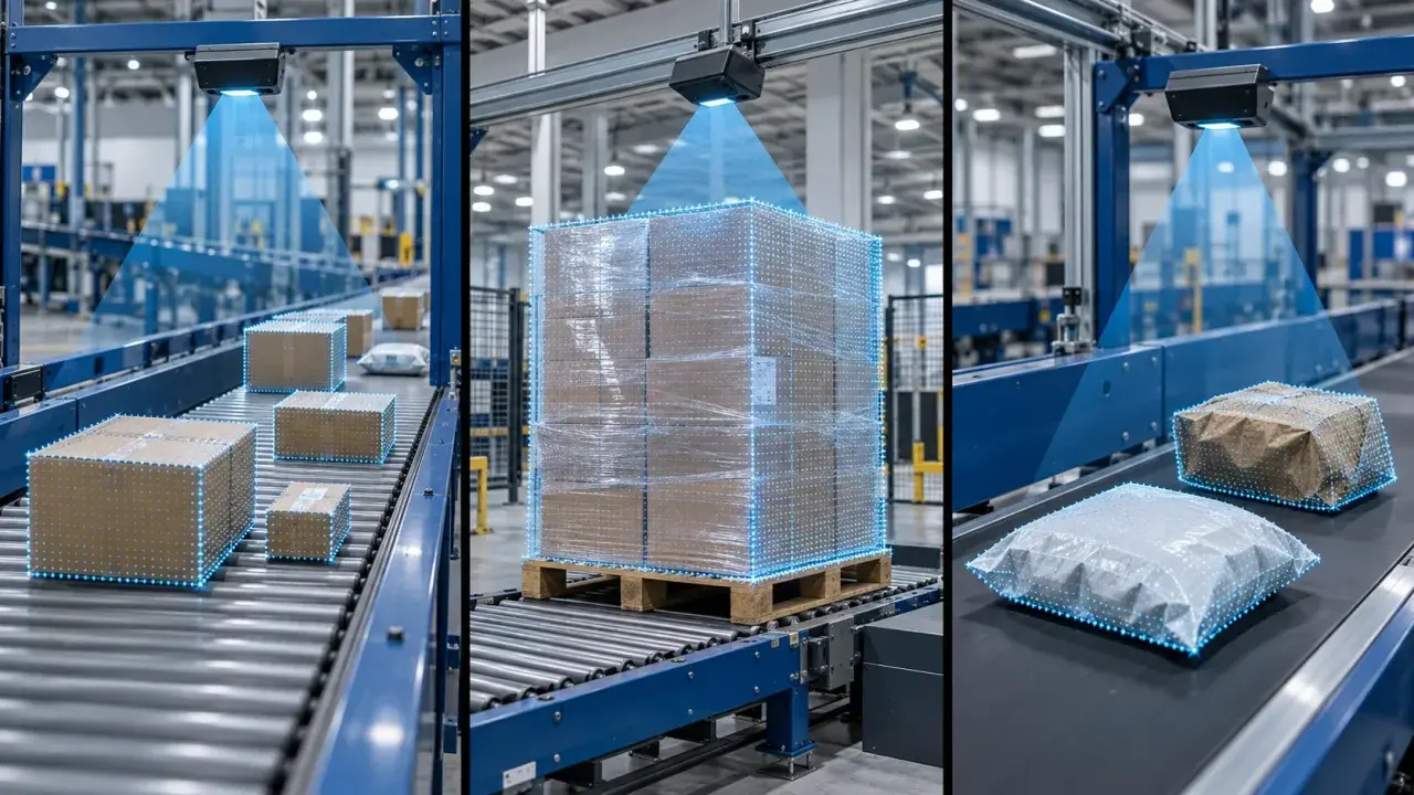
Static stations favor controlled presentation; in-motion conveyor dimensioning adds trigger, line-speed and duplicate-read constraints. Pallet and irregular-object measurement often needs wider coverage or multiple views.
Representative scenes for evaluation. Select the camera layout and geometry model from the target class, material mix and line decision.
Parcel and box dimensioning
Use package dimensioning to measure cartons, mailers and mixed SKUs at a static station or in motion on a conveyor before sortation, storage or carrier rating. Define how labels, tape, void fill and overhangs are treated.
Static dimensioning stations
Conveyor cubing and DWS
Dimensional weight inputs
Pallet dimensioning and load profiling
Build a depth envelope for pallets, totes and stacked loads. Use the result for storage-slot checks, robot hand-off and loading verification.
Pallet height and overhang
Put-away clearance
Load verification
Irregular-object scanning
Use point clouds when a box model is not enough. Validate surface reflectivity, occlusion and the required coverage of the object class.
Bulky goods
Returns inspection
3D inventory records
Engineering reality
Design for the failure surfaces that change volume results
Open each item to connect a ToF limitation with a practical validation action before design freeze.
Line motion and blur
Why it matters
Object speed, vibration and trigger timing affect the number of valid samples available for a stable envelope.
Validation approach
Synchronize capture with the line, define exposure and validate at the fastest production condition.
Dark, glossy or transparent surfaces
Why it matters
Low return signal, specular reflection and transmission can create noisy, displaced or missing depth.
Validation approach
Test the real material mix, log invalid-pixel rate and define an exception path for low-confidence scans.
Occlusion and overhang
Why it matters
A single viewpoint cannot see hidden faces, deep recesses or a parcel that is partly outside the field of view.
Validation approach
Set a controlled measurement zone, use multiple views when needed and reject incomplete silhouettes.
Ambient infrared and interference
Why it matters
Sunlight, nearby emitters and multiple active cameras can reduce signal-to-noise ratio or introduce interference.
Validation approach
Validate under worst-case illumination and qualify camera placement, shielding and coordination in the complete cell.
Mechanical stack-up
Why it matters
Mounting height, cover glass, contamination and thermal drift change the calibrated geometry over time.
Validation approach
Calibrate the final assembly and define cleaning, recalibration and production-test procedures.
Evaluation hardware
Choose a 3D ToF camera for your dimensioning cell
Use these products to build an evaluation path. Product specifications are the source for model-level limits; station-level accuracy still needs scene-specific testing.
Connect dimensioning data to DWS, PLC, WMS and ERP
Define the data contract before you tune the algorithm. Publish validated measurements to a PLC, warehouse management system (WMS), enterprise resource planning (ERP) or transport management system (TMS) without hiding units, confidence or exception state.
Measurement inputs
Depth map or point cloud
Trigger or frame timestamp
Region of interest
Calibration and coordinate frame
Processing path
Segmentation and filtering
Plane and edge fitting
Dimension and volume model
Confidence and exception rules
System outputs
L x W x H with units
Volume and quality flag
Image or depth evidence
PLC, WMS or API payload
ToF volume measurement FAQ
Questions engineers ask before evaluation
Short answers to common questions about accuracy, materials, legal-for-trade boundaries and product selection.
Can a ToF camera measure boxes and parcels in motion on a conveyor?
Yes, when the measurement zone, trigger, working distance, field of view, belt speed and target surfaces are controlled. The host system still needs segmentation, calibration, geometry fitting, object tracking and exception handling. Validate the complete station with representative packages at production speed.
Is a ToF camera the same as a complete DWS dimensioning system?
No. DWS means dimensioning, weighing and scanning. DOMI cameras and integration guidance are building blocks for the dimensioning function; scales, barcode readers, line controls and business-system interfaces are integrated at system level. Legal-for-trade approval, metrology traceability, certification and final system accuracy remain the responsibility of the system integrator and the applicable market authority.
What accuracy can I expect from a ToF volume solution?
There is no single system accuracy that applies to every installation. Performance depends on camera model, distance, field of view, target material, angle, lighting, calibration, mechanics and the volume algorithm. Use published product specifications as a starting point, then run a scene-specific validation.
How should black, reflective or transparent packages be handled?
These materials can reduce returned signal or create ambiguous depth. Test the real packaging mix, monitor valid-pixel coverage and confidence, and define a reject or re-scan path when the scan does not meet the application threshold.
Can one camera measure irregular objects?
A single view can estimate the visible envelope, but hidden faces and occlusions limit completeness. Point-cloud processing and multiple viewpoints can improve coverage. Define the object class and required measurement error before choosing the camera layout.
Can ToF dimensioning support dimensional or volumetric weight calculations?
Yes. The dimensioning pipeline can provide length, width, height and calculated volume to the host system. The applicable carrier divisor, rounding policy, measured weight and chargeable-weight decision should remain explicit in the DWS, WMS, TMS or billing logic.
When should I evaluate ToF instead of stereo vision or laser profiling?
ToF is useful when direct per-pixel depth, compact area capture and low-texture targets matter. Stereo can offer different range or resolution tradeoffs when reliable texture is available, while laser profiling may suit tightly controlled conveyor geometry. Select from material, distance, motion, coverage, ambient light and required system accuracy rather than the sensor label alone.
Which DOMI products should I evaluate first?
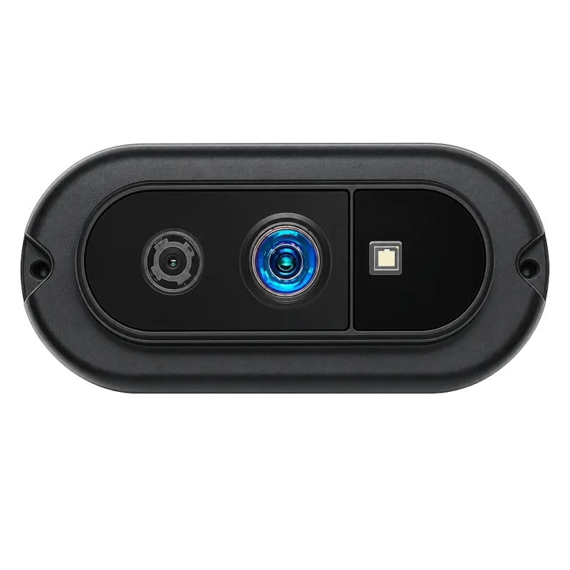
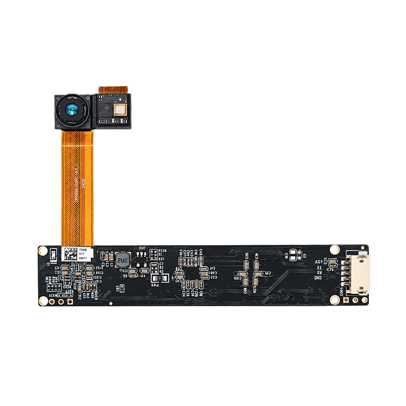
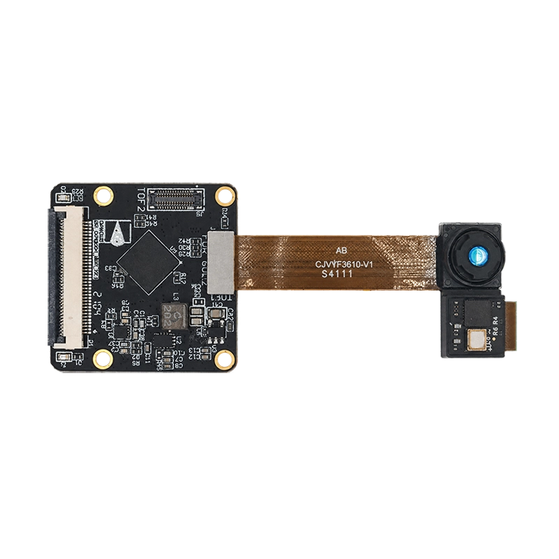
The DM-RGBD5003A is a representative USB RGB-D platform for fast evaluation. Board-level ToF modules such as DM5005A and DMOM2808D can be considered when the product needs an embedded camera path. Confirm interface, range, optics, enclosure and thermal requirements with the final design.
What information helps DOMI recommend a camera?
Share the target size and material, minimum and maximum distance, line speed, field of view, trigger method, ambient light, required dimensions and volume error, host interface, software stack, mechanical envelope and expected production volume.
Discuss your measurement cell
Find the right 3D ToF path for your dimensioning system
Share your target objects, measurement envelope and line conditions. Our team will help review the camera path, station geometry and validation plan.
Camera and field-of-view fit for your measurement zone
Validation priorities for material, motion and calibration
A clear path from depth data to DWS, PLC or WMS integration
Tell us about your measurement application
A few details are enough to start the conversation.