
Smart appliances and touchless HMI
- Gesture control for white goods and smart-home devices
- Multi-zone human sensing and posture-aware interaction
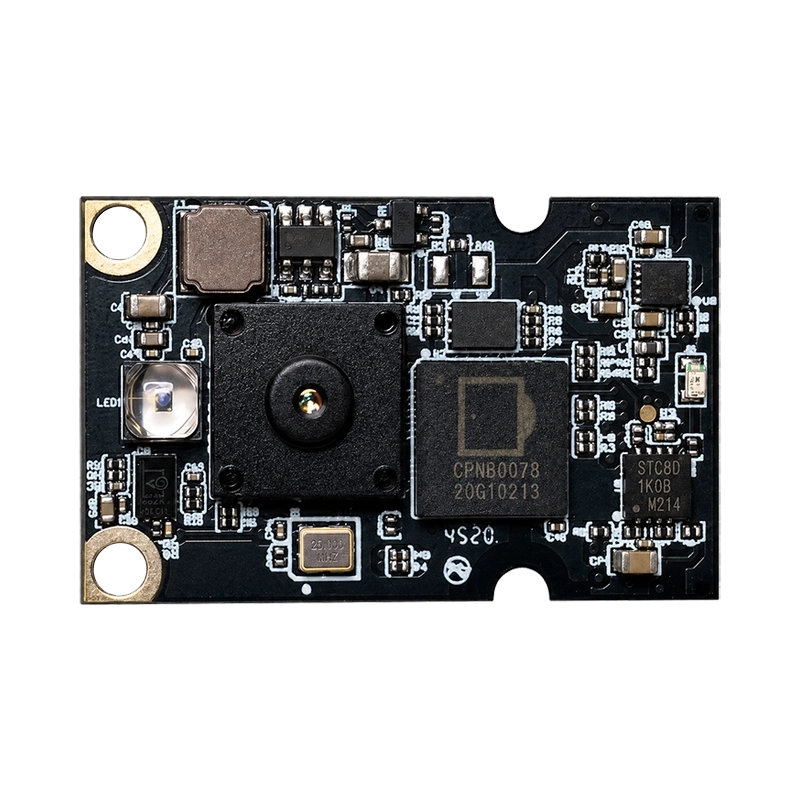
Integrated DM3602 ToF processing, VCSEL illumination and embedded algorithms in a 30.5 × 19 mm board for rapid IoT depth-sensing integration.
Key Highlights
The DOMI DMOS5030A and DMOS5031A are all-in-one 3D Time-of-Flight sensor modules for embedded IoT products. Each board combines a global-shutter 100 × 100 ToF sensor, VCSEL illumination and optics, power management, and a DM3602 processor that handles depth processing and application-specific algorithms.
The integrated Smart ToF ISP and Cortex-M3 core process raw sensor output on the module, then send processed results to the host through a firmware-configurable UART or SPI interface. This architecture can reduce host-side depth-processing work in space-constrained appliances, projectors, access systems and smart-space devices.
Both variants support firmware-configurable output up to 100 × 100 at up to 20 fps and operate from a single 5 V supply. DMOS5030A prioritizes longer range with an 850 nm VCSEL and 30° × 30° field of view. DMOS5031A prioritizes wider near-field coverage with a 940 nm VCSEL and 60° × 60° field of view.
Performance boundary: The stated depth deviation of ≤2% is measured in a darkroom with a target above 85% reflectivity. Ambient light, target reflectivity, motion, cover-window losses, temperature and multi-camera interference can change system results and must be qualified in the final product.
Select the optical variant by working distance, coverage angle and wavelength requirements. The processing architecture, maximum resolution, frame rate, power target and host-interface options are shared.
| Selection parameter | DMOS5030A | DMOS5031A |
|---|---|---|
| Recommended positioning | Longer-range, narrower-FOV sensing | Mid-range, wider-FOV sensing |
| Measurement range | 0.2-4.8 m | 0.2-2.5 m |
| Field of view | 30° H × 30° V | 60° H × 60° V |
| Emitter | 850 nm VCSEL | 940 nm VCSEL |
| Shared output | Up to 100 × 100, up to 20 fps | Up to 100 × 100, up to 20 fps |
| Shared host interface | UART or SPI, firmware configurable | UART or SPI, firmware configurable |
Published values are from datasheet v1.0. Request the latest controlled specification and firmware package before design freeze.
FAE selection note: Choose DMOS5030A when working distance is the main requirement and a 30° field of view covers the target. Choose DMOS5031A when a 60° field of view is more important within 2.5 m or when the system optical stack is designed around 940 nm.
The embedded processor and application algorithms make DMOS5030A/5031A suitable for products that need compact depth sensing and processed results at the host interface.
| Parameter | Datasheet v1.0 specification |
|---|---|
| Sensor | Global shutter, 100 × 100 array |
| Output resolution | Up to 100 × 100, firmware configurable |
| Frame rate | Up to 20 fps, firmware configurable |
| Processor | DM3602 with Smart ToF ISP and Cortex-M3 core |
| Host interface | UART or SPI, firmware configurable |
| Power input | Single 5 V supply, ≥500 mA at CN3 |
| Current consumption | Peak <500 mA; average <200 mA |
| Depth deviation | ≤2% in a darkroom with >85% reflectivity target |
| Mechanical drawing | 30.5 ± 0.2 × 19 ± 0.2 × 3.98 ± 0.2 mm |
| Host connector | CN3, 12-pin, 0.5 mm pitch FPC, back side |
Mechanical-source note: The summary table rounds the board length to 30 mm, while the mechanical drawing specifies 30.5 ± 0.2 mm. The first-page feature list also states 4.05 mm height, while the drawing states 3.98 ± 0.2 mm. Use the drawing as the current layout reference and confirm a controlled mechanical drawing before tooling.
CN3 provides power, host communication, synchronization and GPIO through a 12-pin 0.5 mm pitch FPC connector. Host-facing signals are specified at 3.3 V CMOS level.
| Pin or group | Signal | Integration note |
|---|---|---|
| 1 | VCC_SYS | 5 V supply, rated for at least 500 mA |
| 2 | GND | Ground return |
| 3 | VDD_AP | Reserved; leave not connected |
| 4-7 | SPI_MISO/SDA, SPI_CLK/SCL, SPI_CS, SPI_MOSI | 4-wire SPI; pins 4 and 5 are also labeled for I2C SDA/SCL multiplexing |
| 8 | AP_SYNC/AP_GPIO1 | Host strobe in slave mode or configurable GPIO |
| 9-10 | UART0_RX/AP_GPIO3, UART0_TX/AP_GPIO4 | UART receive and transmit or configurable GPIO |
| 11 | AP_GPIO2 | 3.3 V GPIO |
| 12 | AP_EN | Active-low enable: 0 powers on the module; 1 powers it down |
| UART setting | Published value |
|---|---|
| Signaling | 3.3 V CMOS |
| Baud rate | 115200 bps |
| Frame | 8 data bits, 1 stop bit, no parity |
| Flow control | None |
| Direction | Bidirectional: RX receives configuration; TX outputs processed results |
SPI protocol note: Datasheet v1.0 shows a 4-wire SPI timing diagram but states that the SPI frame format is TBD. Do not freeze the host driver from the timing image alone. Obtain the current command set, framing, clock limits, mode, payload format and firmware compatibility information from DOMI.
Yes. Both variants use a global-shutter 100 × 100 ToF sensor. Output resolution is firmware configurable up to 100 × 100.
Yes. The DMOS5030A specification lists a 0.2-4.8 m measurement range with an 850 nm VCSEL and 30° horizontal × 30° vertical field of view. Validate usable range with the final target and lighting conditions.
Yes. DMOS5031A pairs a 940 nm VCSEL with a 60° horizontal × 60° vertical field of view and a specified 0.2-2.5 m measurement range.
Yes. The integrated DM3602 uses a ToF ISP engine and an on-chip Cortex-M3 core to process sensor data and run application-specific algorithms before sending processed results to the host.
Yes. CN3 pin 1 accepts a 5 V supply rated for at least 500 mA. The datasheet lists peak current below 500 mA and average current below 200 mA, but the complete power budget and transients should be verified in the target duty cycle.
Yes. The host interface is firmware configurable for UART or 4-wire SPI. The v1.0 datasheet marks the SPI frame format as TBD, so request the current firmware protocol before host-driver development.
Yes. The published UART mode uses 3.3 V CMOS signaling, 115200 bps, 8 data bits, one stop bit, no parity and no flow control.
Yes. The datasheet lists multi-zone human sensing, posture monitoring, gesture control, range finding and keystone correction, with application directions including white goods, smart lighting, automatic doors, smart projectors, laser TV and smart parking.
Yes. Datasheet v1.0 states Class 1 laser eye safety and automatic laser shutdown during an abnormal condition. Confirm the applicable standard, certificate scope, firmware behavior and final-product compliance for the exact production configuration.
Yes. CN3 is a 12-pin, 0.5 mm pitch FPC connector on the back of the board. It carries 5 V power, ground, UART, SPI or multiplexed I2C signals, synchronization, GPIO and active-low module enable.
Get expert guidance from our sensing engineers on product selection, evaluation samples, system integration, and technical requirements for your application.